Beam Management
ScanImage uses Laser Beam Modulators to adjust the illumination intensity of the sample. Proper beam modulation ensures that the image contrast is sufficient, while preventing damage of the sample from overexposure.
The configuration of a beam modulator is described in the following section: Beam Modulator Configuration.
Calibration
See the Beams Calibration section in the concepts for a tutorial.
Changing Beam Power
The beam power can be adjusted during an acquisition from the Acquisition Controls Gui window via the slider, the percent power editable text field, or the the left and right buttons.
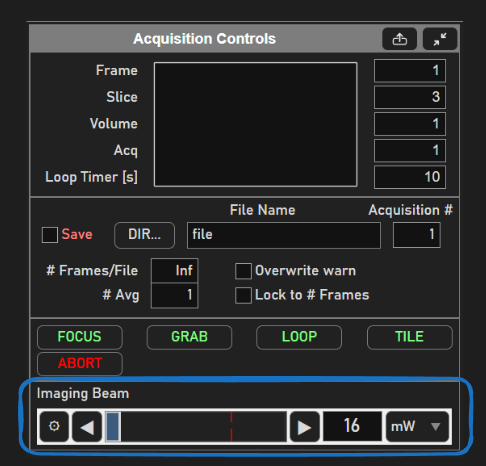
click left or right button |
increment power by 1% of power range |
left-click in power axes |
if left of the current power, decrement by 10%. If right of the current power, increment by 10%. |
left-click and drag in power axes |
instantly set power to percentage of width of axes that the cursor is dragged to. |
Note
During an active acquisition, each time the slider is moved the live output signals are updated. It is more efficient to move the slider to the exact desired position or use the number control than to repeatedly click the slider button.
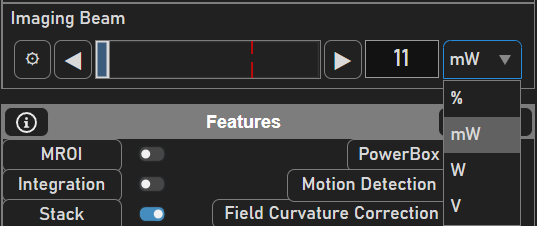
When ScanImage is idle, the beam power can be modulated via the Beam Modulator widget
by clicking and dragging within the rectangular area (similar to previous ScanImage versions’ Direct Mode).
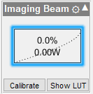
Tip
The widget will always indicate the current output power state of the scope.
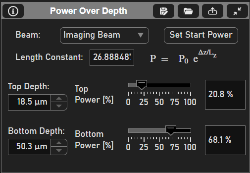
Automatic Depth Power Adjustment
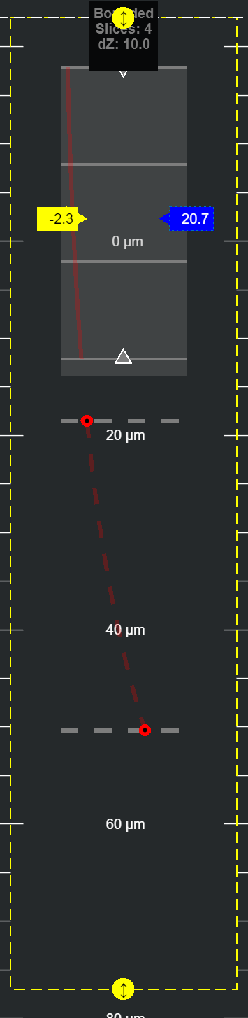
The beam power can be set to automatically vary with depth of the focal plane into the sample to account for power losses within the sample when doing stacks. These features are accessed through the stack tab in the Power vs Depth panel as shown.
Power vs depth uses an exponential function to determine power to be used between a top and bottom depth. The power varies according the following formula:
P0 is the currently selected power at the currently set position of z0.
Lz is a characteristic length constant in micrometers (must be positive)
Note
The Set Start Power button will turn yellow when the start power, P_0 is different from the power required to use the same power curve as was defined when characterizing the characteristic length.
It is not required that you use the same power curve for your next acquisition - turning the button yellow is just a simple indicator. Look at the depiction of the current power curve from the viewport to see if it matches what you desired for the next acquisition.
The P/z Adjust and Lz controls are User Settings, i.e saved/loaded to User (.USR) files. Thus, once value is determined/entered by user for each Beam, these values are typically loaded when ScanImage® starts and apply to all stack configurations/acquisitions during that session.
You can either acquire with exactly the powers used to define the characteristic length, or you can acquire using another p
The top and bottom depths and powers can either be set numerically from the Power Over Depth panel or graphically from the z pane of the viewport.
The beam modulator whose power vs depth is being defined should be selected first from the panel.
To adjust the top and bottom depths for determining the characteristic length from the viewport, the grey, dashed, horizontal lines can be dragged up and down. To adjust the power and the depth for a top or bottom depth, the red dot on the gray dashed line can be dragged horizontally to adjust power and vertically to adjust depth. Dragging the red dot horizontally is the same as clicking and dragging the beams slider.
After configuring the Power vs. Depth, the resultant power profile using the powers defined at the top and bottom can be viewed as the dashed red line in the z view in the viewport.
If the power desired to be used for imaging was used for determining the characteristic length, then the Set Start Power button can be clicked to set P0 for the stack to follow this
curve. Otherwise, if it was desired to use more or less power than was used to calibrate the characteristic length, the characteristic length can still be used, and P0 will just be as was
left in the beams slider in the acquistion controls panel. If the configured start power is different from the start power required to
follow the defined curve, then the Set Start Power button will turn yellow. Regardless, the power to be used in the next stack to be acquired will be displayed graphically
as a solid, red line overlayed over top of the depiction of the stack in the z view of the viewport.
Scanfield Power Boxes
Controlling beam power for specific locations in the scanfield is done with a feature named Power Box.
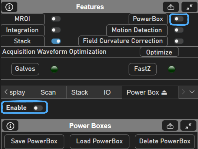
Before enabling power box, click the Power Box in the Features panel to bring up the Power Box tab to configure the power box.
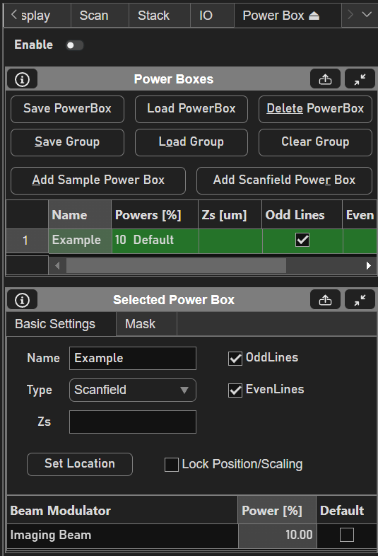
From here a Sample or Scanfield power box can be added. Sample power boxes are a premium feature which can be read about here. Scanfield power boxes are power boxes that are defined relative to the bounds of the ROI’s scanfields.
Note
scanfield power boxes were not developed for use with MROI. It will work, but the same power box pattern will be replicated for each ROI, which in most cases would be unintended.
To add the Scanfield power box, click the Add Scanfield Power Box button.
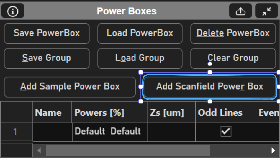
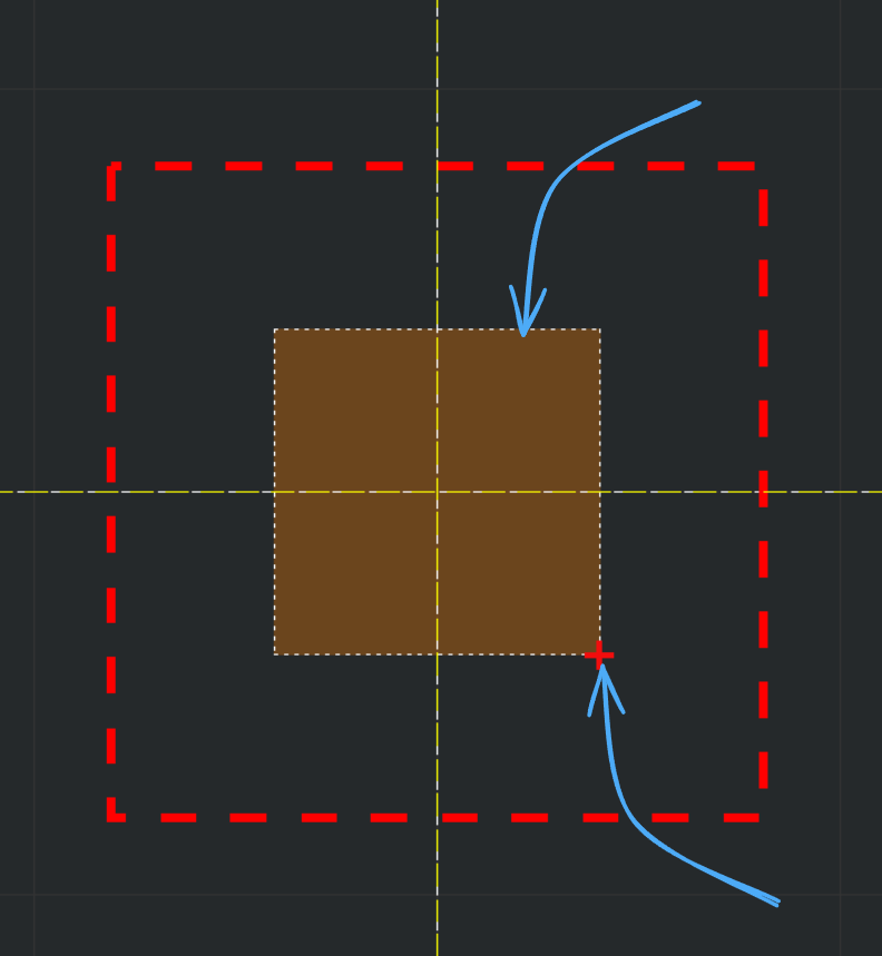
The power box may then be moved and sized to fit a region whose beam power should be different from the rest of the scanfield. Clicking and dragging the outline of the power box will change its position, while clicking and dragging the lower right corner will change its size.
Each of the Power Boxes can have different power levels, which are specified through the table in the Power Boxes Panel or from the table in the Selected Power Box panel. Powers is given as a vector where each index is assigned a beam modulator in the order that they are listed from the Acquistion Controls Panel.
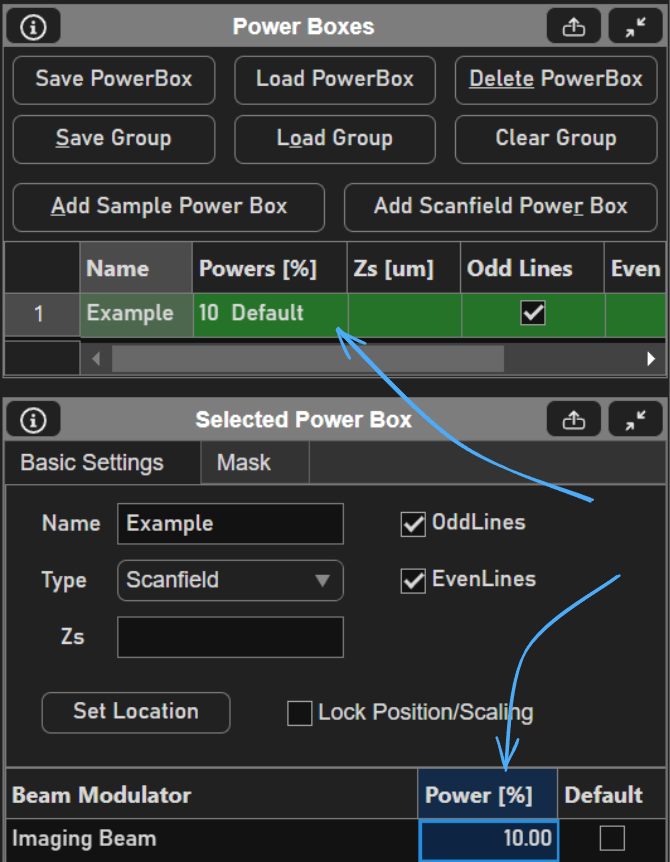
There are several other parameters of power boxes that can be set from the selected power box panel. Review the section for it in it’s tab reference guide page.
Finally, to enable power boxing, click the switch either in the Features panel or at the top of the Power Box tab. Acquisitions started with power boxing enabled will use P0s as configured.
Other Beams Usage
Beams devices play a big role in other features such as Photostimulation and Waveform Optimization. See the below list of pages which use Beams in ways not described here: