Configuring Photon Counting Modules
Attention
This feature is only available with the NI FlexRIO Resonant Scanning imaging system.
ScanImage® can use photon counting modules instead of standard PMTs. A photon counting head / module consists of a PMT and a subsequent photon counting circuit. This circuit generates a TTL pulse of a defined duration when a photon is detected. ScanImage® samples this TTL pulse using the auxiliary digital inputs PFI0-3 of the NI 573x digitizer modules.
Hardware Configuration
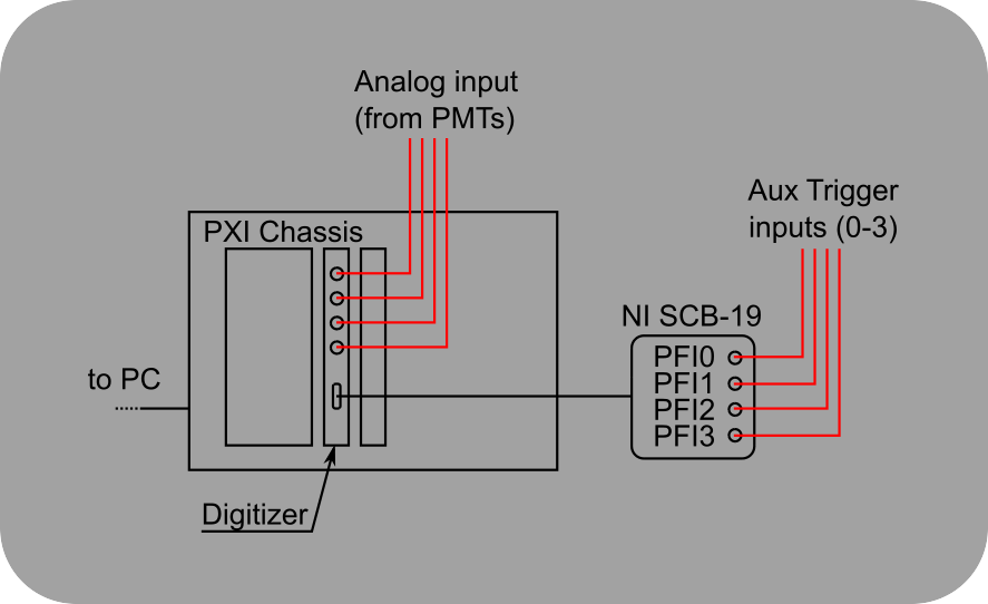
Wiring for Photon Counting Modules
Photon Counting Modules that output a TTL pulse for each detected photon are connected to the digital I/O port on the NI573x digitizer module using a NI SCB-19 breakout box.
ScanImage® Configuration
To configure photon counting for ResScan, add the following entries to the Machine Data File:
%% ResScan

% the features 'Aux Triggering' 'I2C' and 'Photon Counting' are mutually exclusive

I2CEnable = false;

auxTriggersEnable = false;


photonCountingEnable = true; % enable photon counting feature

photonCountingDisableAveraging = true; % disable averaging of samples into pixels; instead accumulate samples

photonCountingScaleByPowerOfTwo = 0; % if photonCountingDisableAveraging == false scale count before averaging to avoid loss of precision by integer division

photonCountingDebounce = 0; % [s] time the TTL input needs to be high before a pulse is registered
The setting photonCountingDebounce can be used to clean up a noisy signal. The delay introduced by photonCountingDebounce can be eliminated by adjusting the value for the scan phase in Configuration Controls.
Limitations
Digitizer Speed
To be detected by the digitizer, the duration of the pulse output by the photon counting module needs to be longer than the sample period of the digitizer module. See the list below for the sample duration of digitizers typically used with ScanImage.
Digitizer |
Sample Rate |
Minimum Pulse Duration |
|---|---|---|
NI 5732 |
80 MHz |
12.5 ns |
NI 5733 |
120 MHz |
8.4 ns |
NI 5734 |
120 MHz |
8.4 ns |
Overlapping Photon Arrivals
Photon Counting Modules cannot discriminate multiple photons arriving in a small time interval. After a photon arrives, the photon counting circuit outputs a high pulse followed by a low signal of a specified duration. During this output time, the photon counting circuit ignores all photons arriving at the PMT.
This makes photon counting modules only suitable for applications where a low photon rate is expected.
Impedance Matching
The digital inputs on the SCB-19 are unterminated single ended inputs. To impedance match the 50Ohm BNC cable used for connecting the photon counting module to the SCB-19 breakout, use a 50Ohm resistor between the PFIx and GND rail of the breakout.