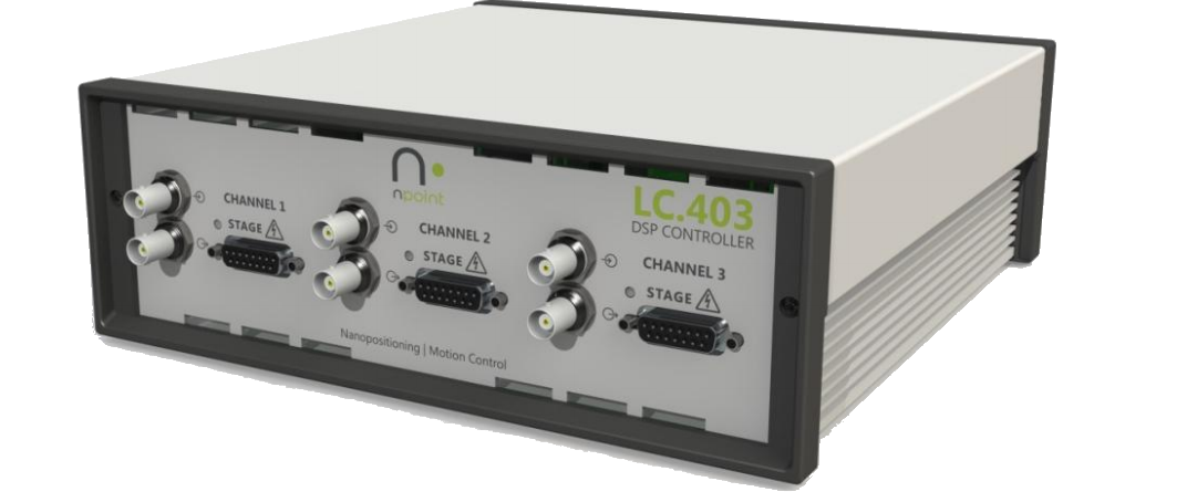
LC40x FastZ
Note
For optimal performance, the LC40x controller PID loop needs to be tuned to the mass of the objective. Consult the LC40x controller manual for more information.
The ScanImage® LC40x nPoint driver sets the LC40x to analog control mode. In this mode the controller reads in an analog control signal on the Position Command Input Terminal to determine the desired actuator position.
Hardware Setup
Connect a USB 2.0 A to B cable between the controller to the PC, and install the nPoint softwaer.
Make the following connection between the controller and the DAQ hardware:
Position Command Input |
Position Feedback Output |
|
Symbol |

|

|
Connect to |
DAQ Analog Output |
DAQ Analog Input |
For vDAQ
Connect a BNC cable from a free analog output on the vDAQ breakout box to the Position Command Input on the controller.
Connect a BNC cable from a free analog input on the vDAQ breakout box to the Position Feedback Output on the controller.
For NI DAQ
A fast focus device runs a DAQ mx timed task, and as such, must not be assigned ports on a DAQ that already has another device with its own timed tasks (e.g. beam modulator or galvo scanner). Once such a DAQ is available:
Connect a BNC cable from a free analog output on the breakout box belonging to that DAQ to the Position Command Input on the controller.
Connect a BNC cable from a free analog input on the breakout box belonging to that DAQ to the Position Feedback Output on the controller.
Once these connections are made, the power cable can be plugged in and the unit turned on.
ScanImage® Configuration
In ScanImage, open the Resource configuration window from the startup dialog or from the Main Controls window under File>Configuration.
From the Resource Configuration window, click the “+” button. Select Fast Focus from the sidebar, and select LC40x FastZ. Give it a name and continue.
A window like shown to the right should appear. Below is a description of each of the configuration parameters
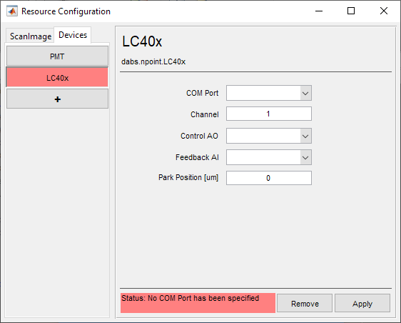
COM Port |
The COM Port that the controller was assigned by the PC. Note To find the COM port assigned to the controller, open the device manager from windows start menu, and expand “Ports (COM & LPT)”. Disconnect the controller USB while watching the device monitor - a COM port will disappear. Reconnect and take note of the COM Port that reappears. |
Channel |
The controller channel to which the fast focus device was connected. This is a number between 1 and 3; enter the channel number that can be read directly from the controller front panel where the device whas connected. This states to the controller which port will have serial and waveform position terms nullified. |
Control AO |
The Analog Output port which was connected to the Position Command Input of the controller. |
Feedback AI |
The Analog Input port which was connected to the Position Feedback Output of the controller. |
Park Position [um] |
The position when not acquiring, i.e. when not acquiring or pointing. |
Click Apply to apply the configuration to this device. It can now be used as a beam modulator for a ScanImage® scanner object.