Stage and Fast Focus Controls
The stage and fast focus devices are controlled within the ScanImage Viewport.
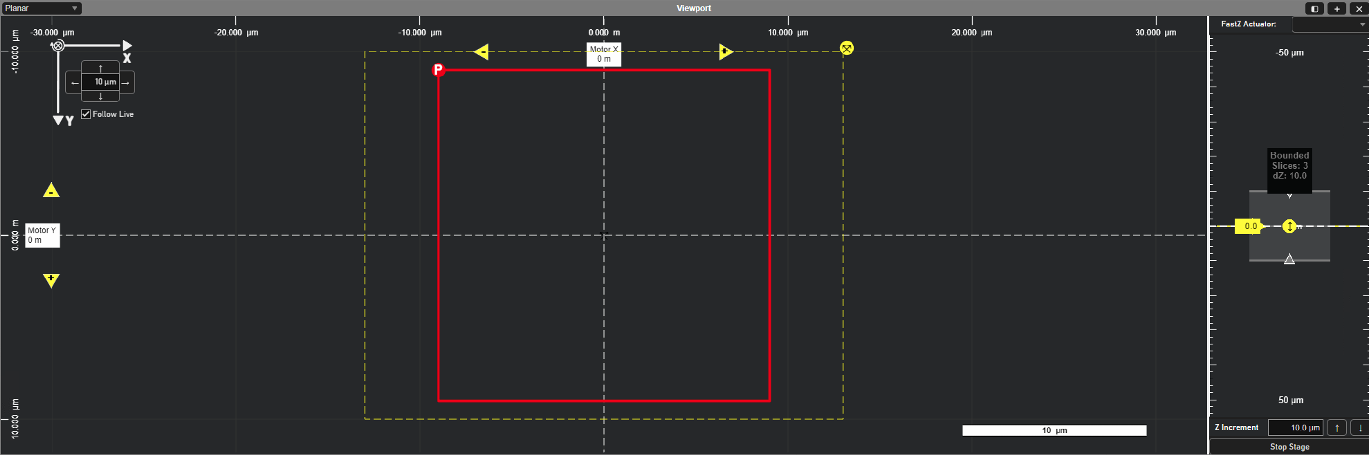
Stage Controls
The stage can be moved in constant increments in X or Y using the yellow arrows.
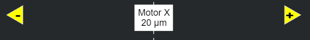
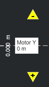
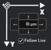
Each click will move the stage by the number of microns specified in the top left controls:
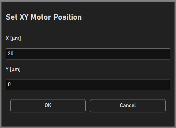
Clicking on the white Motor labels will raise a window to set the desired XY position:
ScanImage will automatically follow XY movements. To toggle this, uncheck ‘Follow Live’.
Note
Stages using the legacy driver will not have live position updating. To read the current position of the stage, click ‘Query Position’ in the Motor Controls window.
The stage can also be moved up and down in Z or be stopped within the ZView:
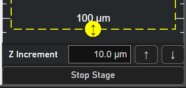
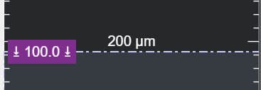
For safety and optimized control, the ZView uses motor limits that prevent the stage from moving beyond a set number of microns. These sliders can be adjusted as desired to restrict or free up stage movement from the Viewport.
Fast Focus Controls
The current fast focus (fastZ) device can be selected via the dropdown in the ZView:
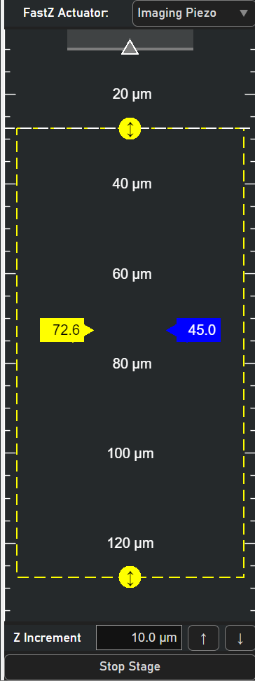
To move the fastZ, click and drag the blue Actuator Slider. Right click the slider to move the fastZ by a specified amount of microns.
The dashed-yellow box illustrates the full fastZ range and overall position in Z. The value in the Actuator Slider is the current depth of the fastZ in microns.
Click and drag the middle mouse button to pan the ZView.