Resonant Scanner
A resonant scanner is scanning device that oscillates the beam-steering mirror in a sinusoidal motion. The position of a resonant scanner cannot be directly controlled. Instead, the resonant scanner generates an end of line trigger (HSYNC), from which the current position of the scanner can be inferred.
A resonant scanner typically has the following control signals:
Signal |
Direction |
Description |
HSYNC |
From scanner |
Digital signal that indicates the completion of one scan period (forward line and backward line) |
Amplitude |
To scanner |
Analog voltage to adjust the amplitude and therefore the width of the scan |
Enable (optional) |
To scanner |
Digital control scanner that enables/disables the scanner |
To learn more about image formation with a resonant scanner, visit the Resonant Scanning Concepts.
Device Compatibility
The Resonant Scanner driver is nonspecific to any model of resonant scanner. The most commonly used resonant scanners are Cambridge Technology CRS Series Resonant Scanners
These models of resonant scanner are often incorporated into a scanhead which is sold as a set of scanners and a controller tuned specifically to the scanhead.
Hardware Config
Connect the resonant scanner or scanhead to the controller.
If using a vDAQ:
Choose a free analog output channel to connect to the controller Zoom input via BNC cable.
Choose a free digital input channel to connect to the controller Synchronization output via BNC cable.
If the controller features an enable/disable pin, connect it to a digital output terminal using a BNC cable (optional).
If using an NI hardware:
On an X-series DAQ, connect the HSYNC signal to an PFIx terminal.
On an X-series DAQ, choose a free analog output channel to connect to the controller amplitude command input.
On an X-series DAQ, connect the controller enable/disable pin to an PFI terminal (optional).
If no other scanners are to be plugged in to the controller, then the controller may be connected to power and turned on.
Software Config
From the Resource Configuration window, under the Devices tab click the add device “+” button.
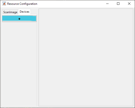
Select Scanner from the sidebar and then Resonant Scanner and click Add. Assign it a name and click OK.
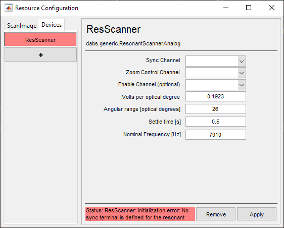
In the window below, configure according to the installed resonant scanner.
Definitions
Sync Channel |
The channel for receiving synchronization pulses which occur once per period of oscillation. |
Zoom Control Channel |
The channel for controlling the amplitude of the scanning |
Enable Channel (optional) |
An optional port for enabling or disabling the resonant scanner. |
Volts per optical degree |
The scaling factor to convert from command voltage to optical degrees |
Angular range [optical degrees] |
The angular range that a beam sweeps as the mirror scans from the CCW and CW extents of its travel. |
Settle time [s] |
The time to wait at the beginning of an acquisition to wait for the resonant mirror to reach a stable operating oscillation and begin frequency measurement. |
Nominal Frequency [Hz] |
A first guess as to the frequency of the resonant scanner. If the measured frequency at the start of an acquisition is to different from this nominal frequency, then an error message will display. |
Note
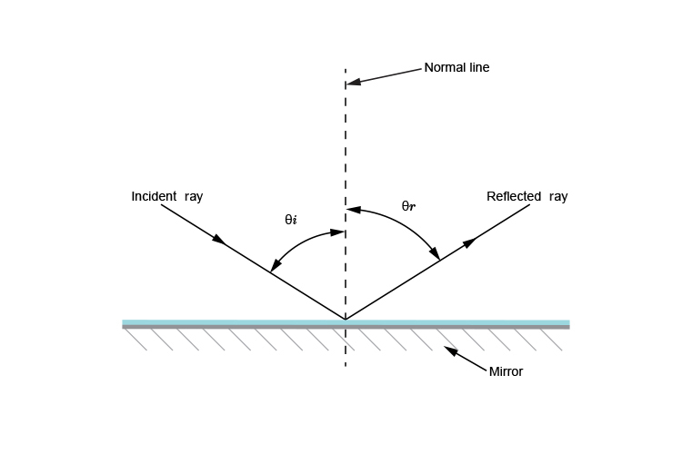
These values are in optical degrees - which is 2x the mechanical rotation angle of the scanner shaft, because of the laser reflection.
Note
Angular Ranges at Zoom=1
Zoom 1 is automatically defined as a square scan of the smaller of the two scanner angular ranges
Tip
It is permissible to use the full angular range of the larger of the two angular ranges, via the ROI/Stimulus Group Editor dialog
Below are recommended settings for various models of resonant scanners
Model |
||
Volts Per Optical Degree |
5V / 26° = 0.1923 V/° |
5V / 10° = 0.5 V/° |
Angular Range [Optical Degrees] |
26° |
10° |
Settling Time [s] |
0.5 |
0.5 |
Nominal Frequency [Hz] |
7,910 |
12,000 |
Resonant Calibration
The amplitude of a resonant scanner does not always change linearly with the control voltage. Since the galvanometric mirror for the scan in y-direction has a linear response, this can lead to an image distorton in x-direction at different zoom levels.
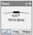
ScanImage® has a built in tool to correct for the non-linear amplitude of the resonant scanner. To access this feature, select the ‘LUT’ button on the resonant scanner widget:
This will show the Resonant FOV to Voltage Calibration Curve, which allows you to manipulate the zoom-to-voltage lookup table for the resonant mirror. After enabling the feature with the checkbox in the lower left corner, start a focus and adjust the zoom level until the distortion becomes visible. In the calibration window, add a control point and adjust the control point’s position using the arrow buttons until the distortion is removed. Repeat the process for multiple zoom levels.
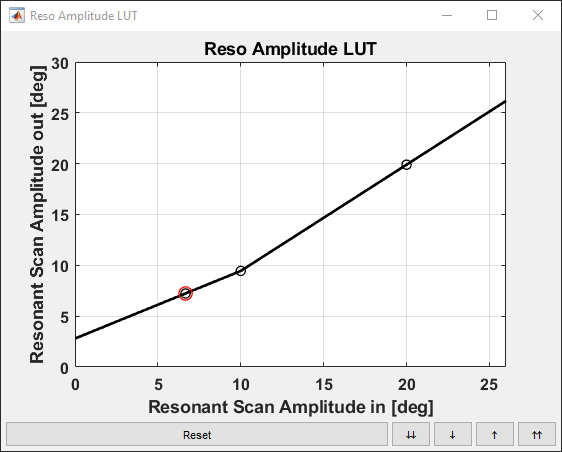
The three knees in the lookup table adjust the voltage for zoom levels 1x, 2x and 3x to compensate for the non-linear amplitude response of the resonant mirror.
Thorlabs GRS8-AG Configuration
Note
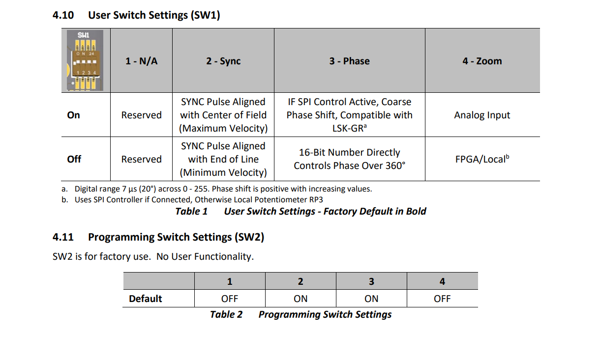
Please visit the Thorlabs GRS8-AG product page, open the manual, and navigate to Section 4.10 User Switch Settings to follow along.
The GRS8-AG has a set of 4 DIP switches (User Switch Settings) inside the driver board. These switches control the User Switch Settings, denoted SW1. All of these switches are by default in the ‘On’ position.
Note
There are two sets of dip switches on the PCB. Look for the the dip switches to the right of ‘SPI’ opening that are hidden behind the covering:
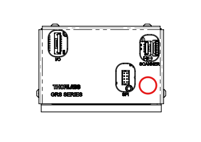
Using a very small Allen wrench (0.7mm), carefully move the second dip switch (SW1.2) to the ‘Off’ position. This is important so the SYNC pulse outputted from the board is aligned with the end of the line instead of the center of the FOV. Otherwise, images will be malformed.
Also, the fourth dip switch (SW1.4) should be in the ‘On’ position so the zoom is controlled by the analog input. This should be the default, but if it is not, move the fourth dip switch to the ‘On’ position.
To summarize, the dip switches should be in the following positions:
SW1.1: N/A
SW1.2: Off
SW1.3: N/A
SW1.4: On
Then, follow the hardware configuration for a typical resonant scanner as outlined above.