Analog PMT Controller
Hardware
This driver can control a PMT high voltage power supply by means of analog / digital control signals. An example for such a power supply is the Janelia PMT Controller.
Warning
Instructions provided here are not a substitute for the user manual provided with the purchased model of PMT and PMT Controller
Connect the controller to the PMT via the provided cables.
If applicable, make connections of DAQ ports to the PMT controller inputs and outputs for:
Gain (AO)
Enable (DO)
Trip Detect (DI)
Trip Reset (DO)
Software
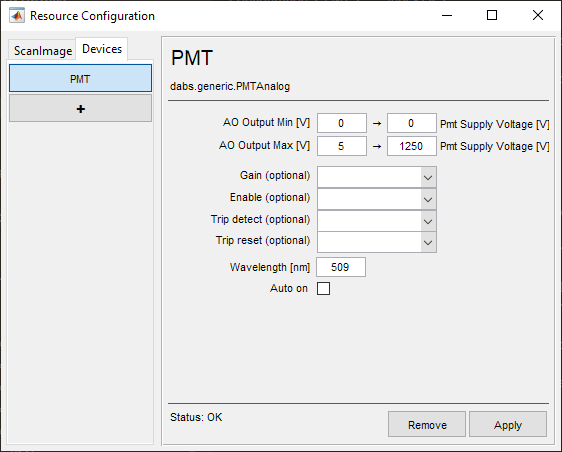
AO Output Min [V] |
The minimum signal voltage to be sent by the DAQ AO |
Minimum Pmt Supply Voltage [V] |
The minimum PMT supply voltage to be supplied for the corresponding AO Output Min. |
AO Output Max [V] |
The maximum signal voltage to be sent by the DAQ AO |
Maximum Pmt Supply Voltage |
The maximum PMT supply voltage to be supplied for the corresponding AO Output Max. |
Gain (optional) |
An optional Analog Output to indicate the PMT supply voltage based on interpolation from the above parameters. |
Enable (optional) |
An optional Digital Output to turn on the PMT |
Trip detect (optional) |
An optional Digital Input to notify ScanImage® of a PMT trip |
Trip reset (optional) |
An optional Digital Output to notify the PMT to reset after a trip. |
Wavelength [nm] |
Peak wavelength sensitivity for this model |
Auto on |
Whether to turn the PMT on or off depending on the Acquisition state. |