Scan Phase
Scan Phase
The resonant scanner outputs a TTL trigger signal when it completes one scanning period. Based on the timing of the period trigger and the selected fill fraction, ScanImage® determines the precise start of each line and switches the Pockels Cells accordingly.
If the period trigger occurs exactly at the maximum deflection of the resonant mirror, the scan phase is 0.
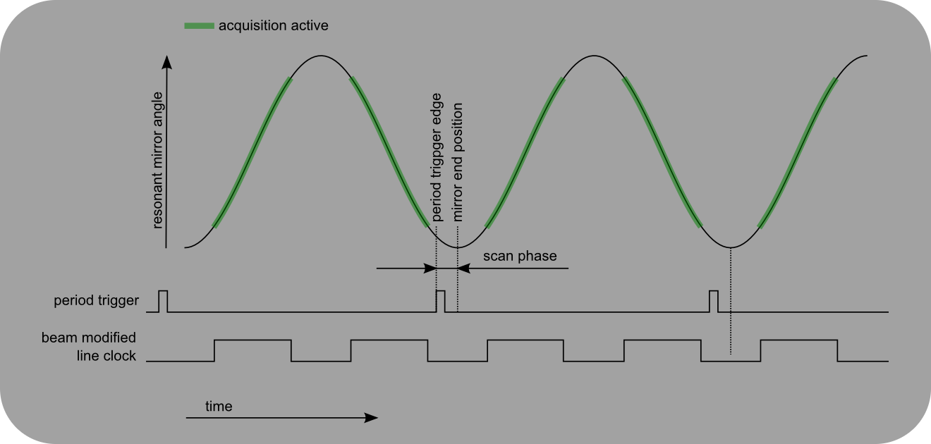
The scan phase is the time difference between the period trigger edge and the maximum deflection of the resonant scanning mirror
Scan Phase Adjustment
By default, the period trigger might not be precisely aligned to the maximum deflection of the resonant mirror. In this case, the lines in the image appear misaligned and the scan phase needs to be adjusted manually. Start a Focus acquisition and open the Configuration Controls dialog. Adjust the scan phase until the lines in the image are aligned. To achieve better results, set the control ‘Rolling Average’ in the Image Controls dialog to 10 or higher, to suppress noise.
The value for the scan phase is measured in units of FPGA ticks. The tick length depends on used FlexRIO digitizer module.
Digitizer Module |
Sampling rate |
Tick length |
|---|---|---|
NI 5732 |
80MHz |
12.5ns |
NI 5734 |
120MHz |
8.33ns |
Warning
The scan phase can depend on the zoom factor and the temperature of the resonant mirror, so that this calibration step might need to be performed repeatedly.
When ‘Focus’ is ended by pressing ‘Abort’ the scan phase value for the current zoom level will be stored automatically. When the zoom factor is changed, ScanImage® will suggest a value based on its internal database. If the suggested value is unsatisfactory, adjust the value manually.
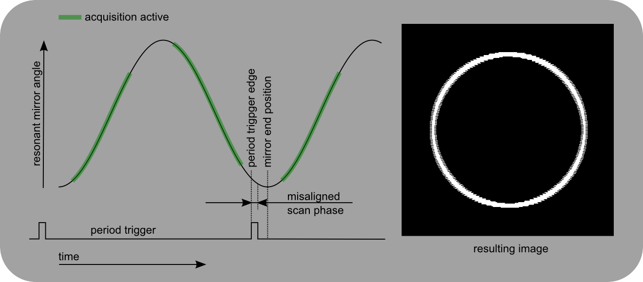
If the value for the scan phase is set incorrectly in bidirectional scanning mode, the lines in the image will be misaligned. If ‘BiDi’ is deselected in Configuration Controls, the image will appear distorted instead.