Auxiliary Trigger
Note
This is a premium feature that is available with vDAQ (RggScan) or resonant scanning with National Instruments hardware (ResScan) only.
To synchronize external events to image data, ScanImage® allows to record precise timestamps for up to four auxiliary digital trigger lines (currently only supported in resonant scanning mode). To achieve the highest temporal resolution and accuracy, the timestamps are generated on the FPGA which is also responsible for image formation.
The timestamps for detected triggers are written to the Tiff header of the frame that was currently being acquired when the trigger occurred. If a trigger occurs in a pause between two acquisitions in Loop mode, the trigger timestamp is written to the first frame of the acquisition following the pause.
The following example shows the Tiff image description for two detected triggers on PFI1.
Tiff header
1Frame Number = 10
2Frame Timestamp(s) = 0.3
3Aux Trigger 0 = [];
4Aux Trigger 1 = [0.313856210 0.331578125];
5Aux Trigger 2 = [];
6Aux Trigger 3 = [];
Auxiliary Trigger Wiring
For the vDAQ, connect the signal carrying wire to the configured port via BNC connection.
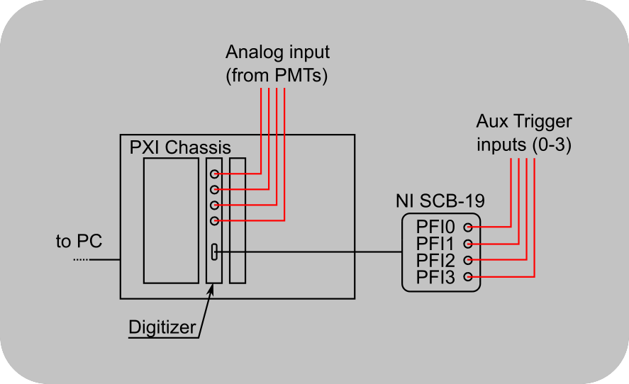
For resonant scanning with National Instruments, an additional NI SCB-19 breakout box is required to feed the trigger input signals through the NI FlexRIO digitizer adapter module (NI5732/NI5734) to the FPGA. Make the connections as shown below:
Debouncing
The temporal resolution of the timestamp is equal to the sample period (Using the internal clock- vDAQ: 8ns, NI5732: 12.5ns, NI5734: 8.33ns). Because of the high sample rate for the trigger lines, noise on the input signal can result in one edge to be registered as multiple triggers. To get around this problem, ScanImage® requires an input line to be stable for a certain time before a trigger is registered. This method is called ‘debouncing’. Since debouncing is a type of low-pass filter, the delay between the occurrence of the trigger and the registration of the trigger would influence the accuracy of the timestamp. However, ScanImage corrects for this delay so that the timestamp accuracy does not suffer from trigger line debouncing.
Note
Debouncing can filter out short trigger pulses. If trigger pulses are lost, it might be necessary to change the debounce time in the ScanImage code.
Open the file +scanimage\+components\+scan2d\+resscan\@Acquisiont\Acquisition.m and locate the property DEBOUNCE_TIME_AUX_TRIGGERS.
Decrease the default value to allow short pulses to be registered as triggers.
Warning
The auxiliary trigger lines are intended to register events and should not be used to record fast external clocks. Currently there is a hard limit for 1000 registered triggers per frame, however it is advised to limit the number of trigger occurrences per frame to around 10.
Debouncing
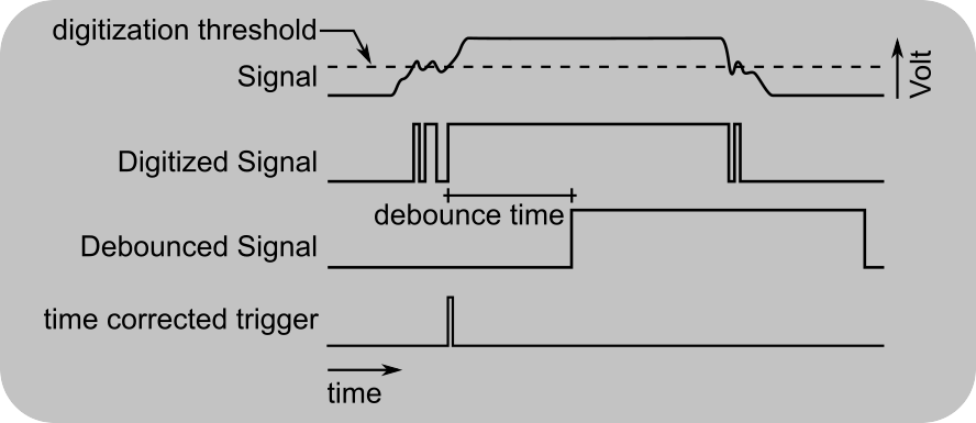
A noisy signal that is digitized at a high rate can lead to multiple trigger edges being registered. The digitized signal is filtered to only allow pulses to pass that exceed a width determined by the debounce time. Since debouncing acts as a low pass filter, the debounced signal is delayed relative to the original signal. To record timestamps with high accuracy, ScanImage® corrects for this delay.