Channels
CHANNELS Panel
Measured voltages for up to 4 input channels are digitized and encoded as values stored in TIF images. These values may be 14-bit or 16-bit signed integers depending on which DAQ you are using.
Note
Negative Intensity?
Data is stored as signed integers, meaning that negative values may be recorded for many pixels. This is done deliberately to ensure the noise histogram is included within the image data-set for cases where the digitizer/detector electronic noise is centered at or near zero. See Offset Correction Notes below.
Per-Channel Controls
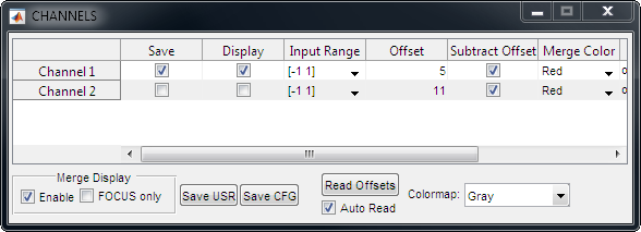
The table reflects/controls properties that pertain to each of the 4 individual input channels supported by ScanImage
Image |
Description |
|---|---|
|
If true, channel data is logged to TIF file during GRAB/LOOP acquisitions Icon Data is saved only if Auto Save is enabled on the Main Controls |
|
If true, channel data is displayed in real-time during acquisition. |
|
Specifies voltage range mapped to input digitization values ranging from -213 to +213 (ScanImage® uses a 14-bit signed data representation). For example, a value of [ -1 1 ] means -1.0V volts equals - 213 ,while a value of +1.0V equals +213. Icon Negative input voltages are also digitized, and mapped to range -2 13 - 0. See Offset Correction Notes below. |
|
Last measured offset value for each channel, in input digitizer units. Values are NaN if no offset values have been measured. Icon The offset is a measurement of the PMT signal when no photons are detected. See Offset Correction Notes for more details. |
|
If true, last measured offset value is subtracted from both displayed and/or saved data for that channel. See Offset Correction Notes below. Icon Offset subtraction is not performed if no offset value has been measured (i.e. if values are NaN). |
|
If channel Merge display is enabled, specifies which color is used to represent image data for specified channel |
|
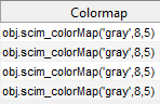
Function to call (on MATLAB path) that specifies colormap encoding of input digitizer values spanning from Black to White values (set on Image Controls panel) for specified channel Note Colormap control shown below can be used to automatically set functions for each channel to commonly used settings. |


Merge Display Controls
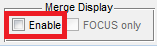
The Channel Merge display can be used to visualize multi-channel data during live acquisition within a single image display figure, by encoding each channel’s data with a distinct color.
|
Shows and activates Channel Merge display figure for subsequent acquisitions |
|
If true, Channel Merge display is only updated live during FOCUS acquisitions Icon Channel Merge applications is often needed only during FOCUS, e.g. for guiding pipette placement. Disabling Channel Merge during actual GRAB/LOOP acquisitions preserves CPU processing for other higher-priority requirements. This checkbox is disabled unless the Merge Enable checkbox is checked. Icon |

Other Channel Controls
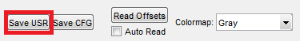
|
Save current user settings to currently loaded USR file. |
|
Save current configuration to currently loaded Configuration (CFG) file. |
|
Reads offset value on each of the input channels. Measurement occurs with scanner parked and with shutter (if used) closed and beam modulation (if used) fully attenuated. Read about PMT Signal Offset Correc tion in the Concepts Guide. |
|
If true, offset values are read on each input channel prior to start of each acquisition (FOCUS, GRAB, or LOOP) before opening the shutter Icon Auto Read value is a User Setting - i.e. saved as part of the USR file typically loaded on ScanImage® startup - and applying to all ScanImage® Configurations (CFG files) |
|
Specify colormap scheme to use for input channels. Selecting values is a ‘macro’ that automatically overwrites the per -channel Colormap function values. |