Line Scanning Channel Display Window
Introduction
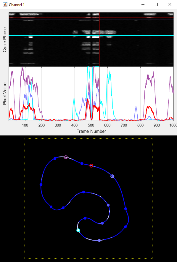
The line scanning channel display contains multiple elements to help visualize the data collected while using the arbitrary line scanning feature. The three main displays are the full data view, the time plot, and the spatial view. If the window is sized in landscape orientation, the full data view will be at the top left, time plot on the bottom left, and spatial view at the right. If the window is sized in portrait orientation, the full data view will be at the, time plot below, and spatial view at the bottom (as seen in the screen shot on the right).
Full Data View
The full data view is a heat map showing history of data collected over the specified history length. The history length can be controlled from the IMAGE CONTROLS interface. The vertical axis represents cycle phase. A vertical line of data in the heat map represents the fluorescence data collected over a single cycle of the scan path. The horizontal axis represents frame (cycle) number. This is essentially the time axis. A horizontal line of data from the heat map represents fluorescence data collected over the history of frames at a single point of the scan path. If you were interested in how the fluorescence of a particular ROI was changing over time, you would look at a horizontal line of data. The full data view provides a way to see an overview of how all ROIs are changing over time. The pixel value from the collected fluorescence data is scaled to the heat map color using the lookup table White/Black values from the IMAGE CONTROLS interface.
Time Plot
The time plot allows you to select individual ROIs to plot over time for easier viewing. Each plot in the time plot view shows data for a single point in the scan path over the frame history. If the mouse hovers over the full data view or spatial view, the plot for the corresponding point is shown in the time plot view in red. If you click on the full data view or spatial view, the corresponding point will be added to stay in the time plot even when the mouse is not hovering. The vertical axis of the time plot is set by the lookup table White/Black values from the IMAGE CONTROLS interface.
Spatial View
The spatial view shows data from the latest completed cycle in the context of the actual scan path. This is depicted by a blue/white data line. The color of the line indicates the fluorescence measured at that point in the path. Blue corresponds to the black value from the IMAGE CONTROLS interface while white indicates the white value from the IMAGE CONTROLS interface. If the designed scan path includes any point or waypoint elements, they are indicated as bold points in the display.
If scanner position monitoring is enabled, the designed scan path is shown in white dotted lines while the data line shows the actual path of the scan mirrors. A large deviation of the actual path from the designed path could indicate that the designed path is too demanding for the scan mirrors to keep up with.