Thorlabs MCM 6000
Hardware Config
Warning
Instructions here are no substitute for instructions that can be found in the product manual. Follow at your own risk.
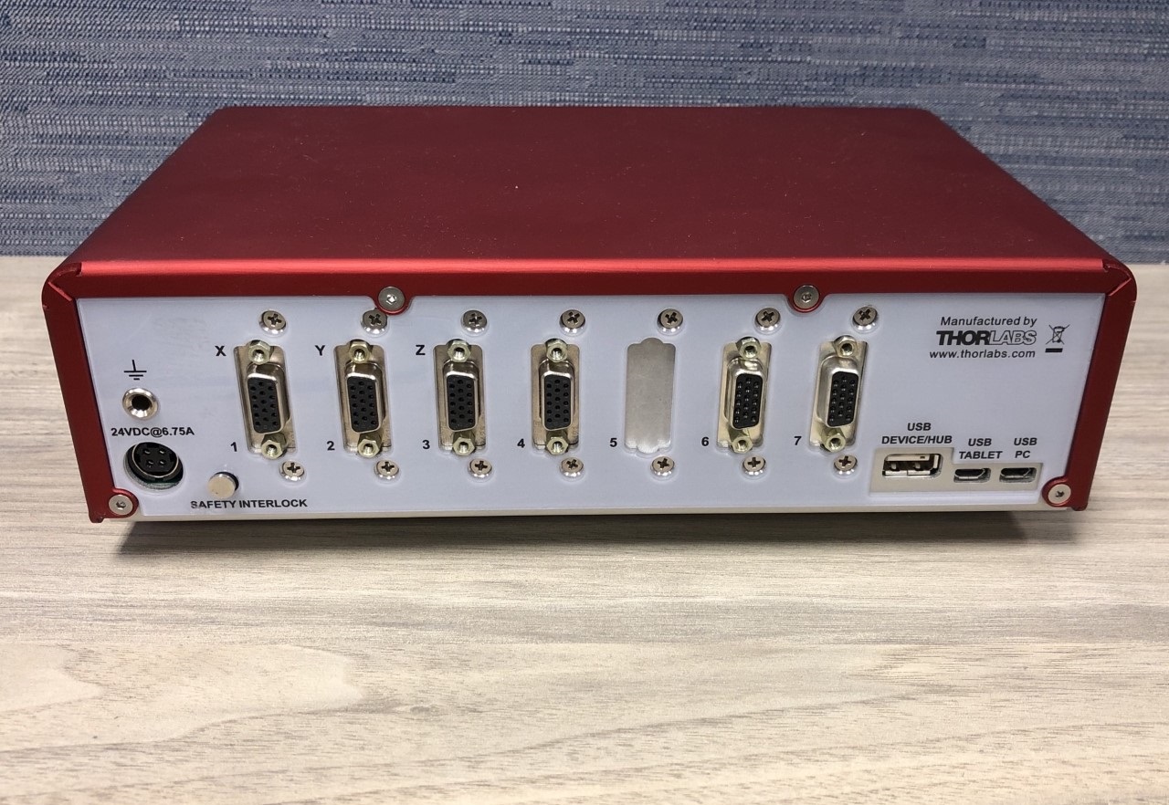
Utilizing the D-Type connector cables provided by Thorlabs, connect the desired axes, shutter, and flipper mirror control to the MCM-6000 ECU. There should be as many cables as there are axes to be controlled.
The Motor axes should be labeled by other ports may not be. Refer to the Software Configuration Guide below or Thorlabs support for details on which port controls what.
Connect 1 USB Micro to USB cable to the port labeled “USB PC” - This will provide a COM port for ScanImage communication. A USB Device/HUB port is also provided that may be used for monitoring communication.
Connect 1 USB Mirco to USB cable between the port labeled “USB Tablet” and the Thorlabs provided control Tablet if applicable.
Connect the provided Thorlabs AC power supply cable to the power port. Refer to the Thorlabs manual for setting up the grounding Pin and Interlock Saftey.
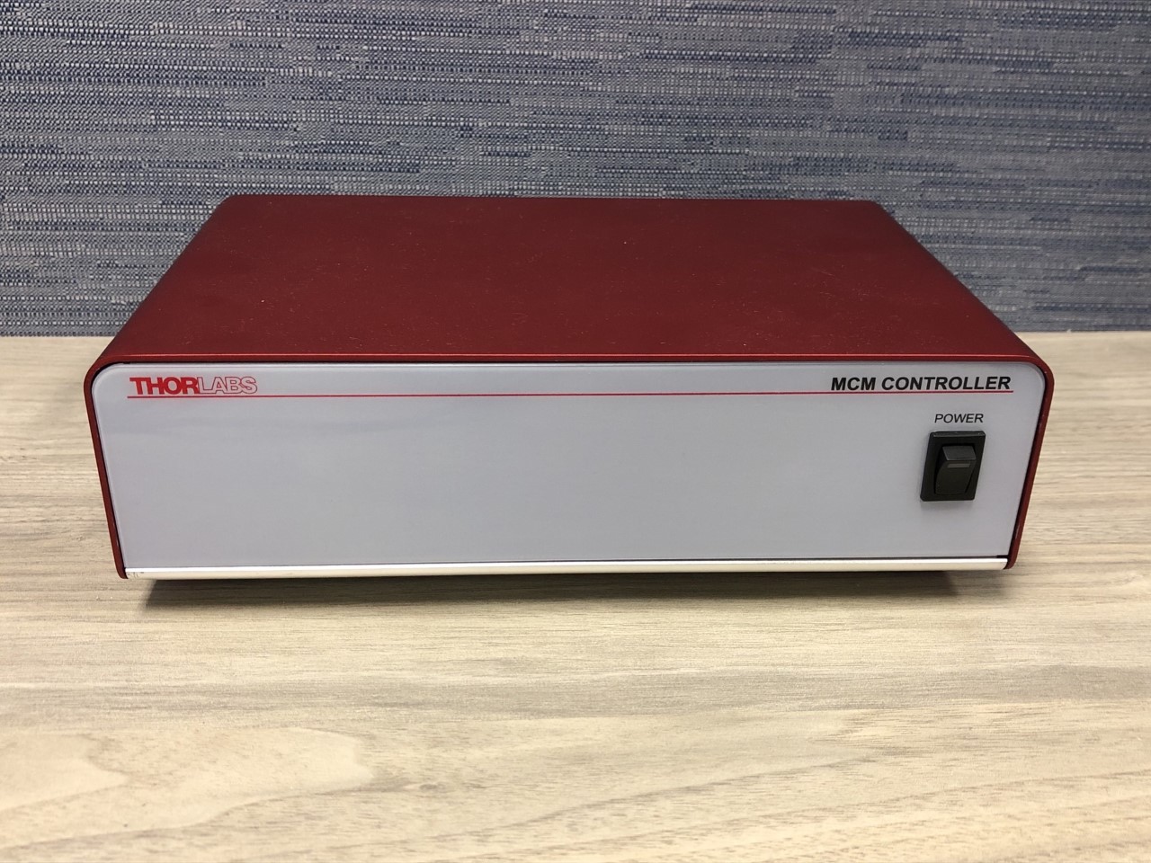
Flip the power switch on the front of the ECU to power the device.
Software Config
In ScanImage, open the Resource Configuration window from the startup dialog or from the Main Controls window under File>Configuration.
From the Resource Configuration window, click the “+” button. Select Motor Controller from the sidebar, and select Thorlabs MCM-6000 Redbox. Give it a name and continue.
A window like shown below will be displayed. Below the image is a description of each of the configuration parameters
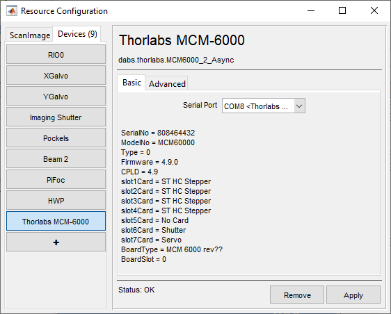
Serial Port |
Select the COM port assigned to the computer. This COM port should reference the USB to PC connection mentioned above. Once applied a hardware device information list will appear. This will list card slots and their controls. Here you can see that Slot6 is the Shutter card and Slot7 is the Servo card. Note The COM port can be determined by powering off and disconnecting the USB cable for the controller, and then watch the windows device manager under Ports (COM & LPT) while reconnecting and powering on the controller to see which COM Port is established. |
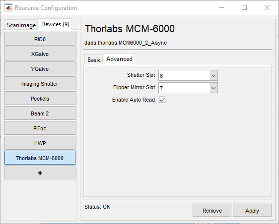
Shutter Slot |
Here you can provide the device slot that the shutter control card uses. This will tell ScanImage which device address on the ECU to direct shutter control messages to. |
Flipper Mirror Slot |
Here you can provide the device slot that the flipper mirror control card uses. This will tell ScanImage which device address on the ECU to direct mirror control messages to. |
Auto Read |
This enables or disables live position reading. Turning this off may improve performance for some users. |
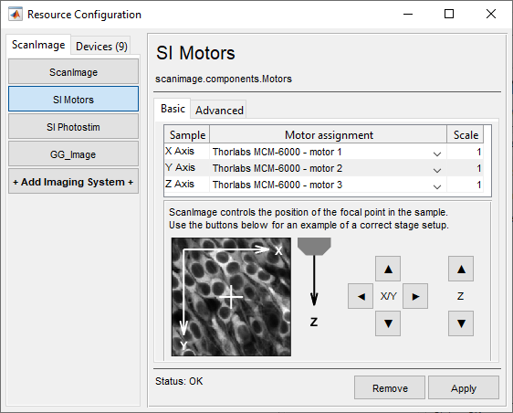
Once the device has been configured, it can be added to the ScanImage® imaging system via the left pane of the Resource Configuration window under the ScanImage tab after clicking the SI Motors button. This will reveal a page (see below) that will allow each of the axes to be configured as a MCM-6000 axis.
Scaling factors are provided in addition to the configuration settings.
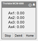
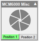
The MCM-6000 will also create 2 widgets on the ScanImage widget bar. These are the standard motor control widget and the MCM 6000 Misc widget. The former is modified to notify the user when the axes are moving, or at limit. Users can also click axes to disable them. The latter will give users control over the shutter and the flipper mirror positions.
|