Generic Polygonal Scanner
Note
This ScanImage device is supported on the vDAQ only.
A polygonal scanner is scanning device that rotates the beam-steering polygonal mirror (polygon where each side is a mirror) at a constant speed. The angular position of a polygonal resonant scanner cannot be directly controlled. Instead, the polygonal scanner can output a start of scan (SOS) signal (or one can be made with an alignment laser and photodiode), or similar signal from which the current position of the scanner can be inferred.
A polygonal scanner typically has the following control signals:
Signal |
Direction |
Description |
HSYNC |
From scanner |
Digital signal that indicates the start of the next scanned line. |
Speed Control |
To scanner |
Square Wave of a certain frequency to set the speed of the polygonal scanner |
Enable (optional) |
To scanner |
Digital control that enables/disables the scanner |
The polygonal scanner shares traits of both resonant and galvo scanners.
Similarities to galvo scanners:
angular velocity is constant during acquisition of the line, thus a uniform pixel binning is used in contrast to resonant scanning’s sinusoidal pixel binning
Similarity to resanant scanners:
high line rates
angular position must be inferred from a synchronization signal
ScanImage cannot ensure that the duration of time for scanning the line is an integer sub-multiple of the acquisition sample rate. Thus, acquisition sample rate does not drive frame rate.
Polygonal Scanners differ from both galvo and resonant scanners in that:
They cannot scan bidirectionally
Changing the size and location of the field of view must be done through alteration of acquisition details rather than a changes to a control signal.
Due to the last point, the MROI feature or steering and zoom elements of the main controls window are disabled when polygonal scanning.
Device Compatibility
The generic polygonal scanner driver is nonspecific to any model of polygonal scanner. It can (optionally provide) a TTL signal for speed control and enabling the scanner. A line clock is required for synchronization between acquisition and scanning where the rise of the signal roughly corresponds to the start of the scanned line. Scan phase adjustment can accommodate lag or lead of the sync signal relative to the actual start of scan.
ScanImage can support line rates from 2000 Hz to 15000 Hz. Whichever combination of mirror facets and speed capabilities achieves a line rate in this range does not matter to ScanImage. Many polygonal scanner drivers do not accept a line rate signal to determine the scan speed; instead, the frequency of the square wave required to achieve a certain line rate is some factor times the line rate. ScanImage provides an Output Frequency/Line Rate Ratio setting so that the required square wave can be output from a digital output port on the vDAQ.
Hardware Config
Connect the polygonal scanner to the polygonal scanner controller according to the vender provided manual. If the controller can be configured to output a start of scan signal, then configure it this way. If the controller cannot be configured this way, then a photodiode and alignment laser need to be arranged so that a start of scan signal can be generated. Feed this signal to a digital input of the vDAQ and take note of the port for later software configuration.
If using the driver to control the speed of the polygonal scanner, connect a digital output port of the vDAQ to speed control input of the polygonal scanner controller.
If using the driver to control the enable state of the polygonal scanner, connect a digital output port of the vDAQ to enable input of the polygonal scanner controller.
Software Config
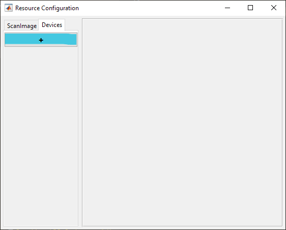
From the Resource Configuration window, under the Devices tab click the add device “+” button.
Select Scanner from the sidebar and then Generic Polygonal Scanner and click Add. Assign it a name and click OK.
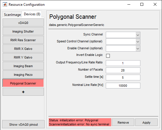
In the window, configure according to the installed polygonal scanner and connections made.
Definitions
Sync Channel |
The channel for receiving synchronization pulses which occur once per scanned line (side of polygonal mirror). |
Speed Control Channel |
An optional channel for controlling the speed of the scanning. |
Enable Channel (optional) |
An optional port for enabling or disabling the resonant scanner. |
Invert Enable Logic |
If the polygonal scanner controller requires 0V to enable the scanner, then place a check in this box. |
Output Frequency / Line Rate Ratio |
The quotient calculated by dividing the frequency of square wave you need to output by the desired line rate. |
Number of Facets |
The number of mirror facets on the mirror (# of sides of the polygon) The greatest angular range that a beam sweeps as the mirror scans is derived from this. |
Settle time [s] |
The time to wait at the beginning of an acquisition to wait for the polygonal mirror to reach a stable operating speed and begin line rate measurement. |
Nominal Frequency [Hz] |
The Nominal line rate of the polygonal scanner. If the measured line rate at the start of an acquisition is too different from this nominal frequency, then an error message will display. |
Acquiring with the Polygonal Scanner
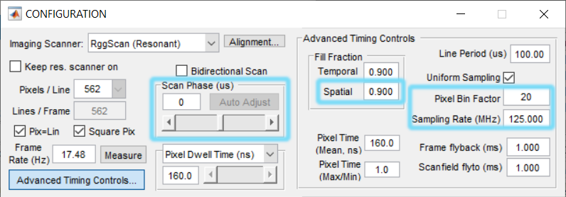
Since the polygonal scanner always scans the laser across a set angular range, acquiring smaller FOV or laterally positioning the FOV must be achieved by tweaking acquisition settings.
The width of the acquired image corresponds to the spatial fill fraction. A value of 1 would be the entire angular range, but this is not a practical value as samples could overlap between the end of one line and the start of another.
The lateral position of the FOV depends on the scan phase offset and the rise of the sync pulse relative to the actual start of the line. The scan phase adjustment can be leveraged to steer a small fill fraction acquisition to different parts of the acquirable field of view.
Polygonal scanning uses uniform sample binning. The product of the pixel bin factor (samples per pixel) and the sampling rate thus determines the pixel resolution of the line.