PI GCS2
PI GCS1 driver supports the following PI controller models:
E709
E709.CHG
E753
Hardware Configuration
Connect the piezo objective stage to the controller via supplied cable
Connect the controller to the PC via USB.
Use SMA to BNC cables to connect the command input of the controller to a free analog output on the DAQ.
Do the same from the monitor output of the controller to a free analog input on the DAQ.
Note
if using NI DAQ hardware, ensure that the the fast focus device is connected to a DAQ board which is not controlling any other devices which utilize timed tasks, such as the resonant scanner or beam modulators.
Connect the controller to power, and turn on.
ScanImage® Configuration
In ScanImage, open the Resource configuration window from the launch window or from the Main Controls window under File>Configuration.
From the Resource Configuration window, click the “+” button. Select Fast Focus from the sidebar, and select the driver with the same name as the used controller. Give it a name and continue.
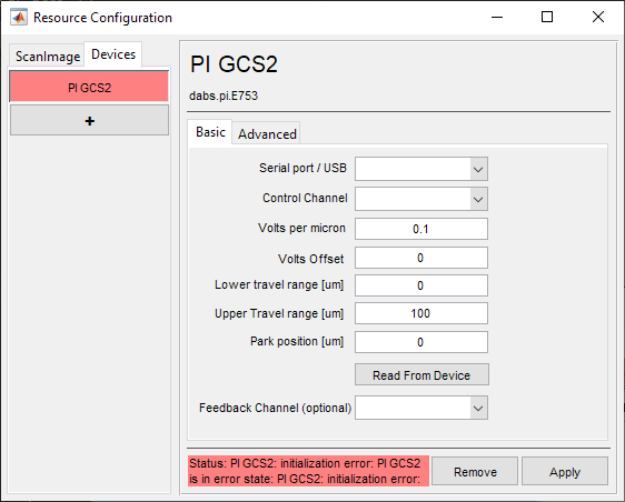
A window like shown below should appear. Below is a description of each of the configuration parameters
Basic Page |
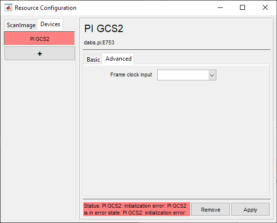
Advanced Page |
|
|
Basic Configuration
Serial port / USB |
Select COM port assigned to the controller by the computer. Note The COM port can be found by opening Windows Device Manager under Ports and LPT and unplugging and replugging in the USB for the controller. This will make the COM port corresponding to the controller disappear and reappear, respectively. |
Control Channel |
The Analog Output port which was connected to the Position Command Input of the controller. |
Volts per micron |
Assuming a linear control relationship, this is increment in command voltage required to increment the focus depth by 1 micron. |
Volts Offset |
The voltage at which ScanImage® coordinate system will define the depth as being 0 um. |
Lower travel range [um] |
The lowest (most negative) extent of the device’s travel. |
Upper travel range [um] |
This is highest (most positive) extent of the device’s travel. |
Park position [um] |
The position when not acquiring, i.e. when not acquiring or pointing. |
Feedback Channel (optional) |
The Analog Input port which was connected to the Position Feedback Output of the controller. |
Note
Use the Read From Device button to read parameters straight from the controller.
Advanced Configuration
Frame clock input |
This is the Digital Input port which will receive the frame clock signal |
Click Apply to apply the configuration to this device. It can now be used as a beam modulator for a ScanImage® scanner object.