Beam Router
Optical Configuration
The pockels cells can be arranged in a way that was planned for in a custom made function handle.
Hardware Configuration
Connect BNC cables between the pockels cells’ driver’s command inputs and DAQ outputs.
Connect BNC cables between the pockels cells’ driver’s feedback outputs and DAQ inputs.
Note
If using NI hardware, pockels cells can be connected to the same DAQ since they share the same timed task.
ScanImage® Configuration
Select the “+” button and select Beam Router from the Beam Modulators sidebar tab. This adds the Beam Router device configuration page to the Resource Configuration window.
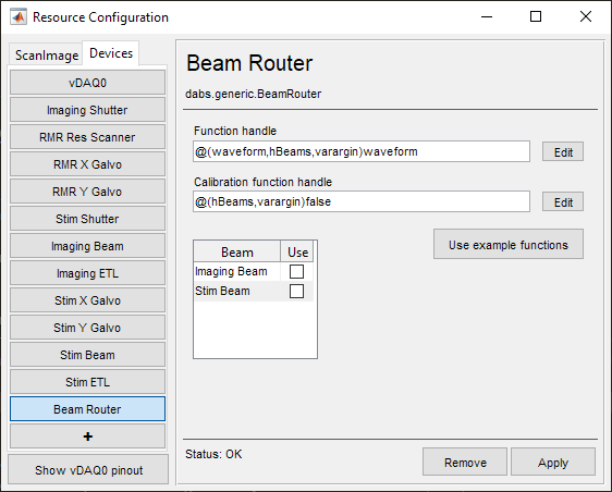
Function handle |
This is a function handle for handling the pockels cells devices. It should assume an optical configuration. |
Calibration function handle |
This is a function handle for calibrating each of the pockels cells associated with the Beam Router. |
Beam |
Select the previously configured Beam Modulator to use |
Tip
The “Use example functions” button will load example functions.
You can look at the example functions for ideas, and also use them as templates for custom functions.
Simulated Tutorial
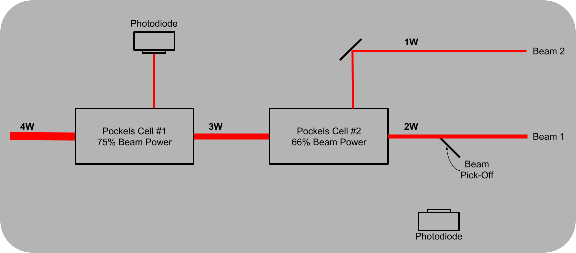
In this tutorial, a beam router uses two pockels cells to be able to set the power of two beams coming from one source. One for setting total power into the second pockels cells, and the second for dividing that resultant beam into two beam paths.
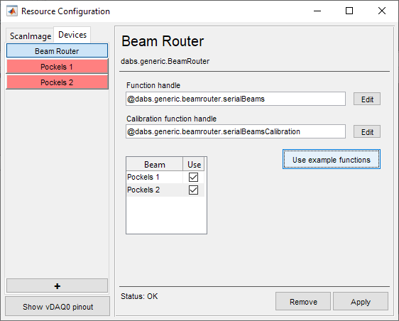
The Beam Router can be used to pair Beam Modulators in any fashion of the user’s design, but to implement the described optical configuration, click the Use example functions button. This opens the +dabs/+generic/+beamrouter/serialBeams.m and +dabs/+generic/+beamrouter/serialBeamsCalibration.m files which describe how the pockels cells are intended to be used.
These files are assigned in the Resource Configuration window as handle functions. Clicking the Use example functions button also adds additional Pockels 1 and Pockels 2 devices to the device list. Make sure that those beam modulators are enabled.
|
|
Note
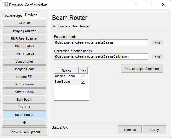
The order that the beam modulators are listed is important in determining which beam modulator is filling which role. In this case, the Imaging Beam selected in the Beam Router page is the pockels cell which determines how much total power is split (beam1 in +dabs/+generic/+beamrouter/serialBeams.m, line 20). The Stim Beam is the pockels cell which determines the division of beam power between imaging systems (beam2 in +dabs/+generic/+beamrouter/serialBeams.m, line 21).
Go to the ScanImage tab of the Resource Configuration window. Select or add an imaging system. You will notice that the Pockels 1 and Pockels 2 are options for the beam modulators. Here, in the imaging system configuration, Pockels 1 actually represents B1 from the Widget Bar, and Pockels 2 represents B2. Configure imaging systems accordingly.