Trigger Controls
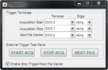
TRIGGERS Panel
Description
Assign and configure External Trigger signals to synchronize image acquisition with experimental events.
To open this dialog, select the menu item from the Main Controls >> Settings Menu >> Triggers…
The terminals available in the External Trigger Configuration depends on the “digitalIODeviceName” variable in the Machine Data File . The following table describes what terminals are available:
Type ofdigitialIODeviceName |
Available Trigger Terminals |
Notes |
DAQmx Device |
PFI1 |
Usually connected to a PXIe Data Acquisition Card (e.g. NI PXIe-635 6 or NI PXIe-6341). These correspond to the PFI terminals on the to use for external triggering. |
PFI2 |
||
PFI3 |
||
PFI4 |
||
FPGA/RIO Device |
DIO0.0 |
Usually connected to a National Instruments SCB-68 A or other terminal block. |
DIO0.1 |
||
DIO0.2 |
||
DIO0.3 |
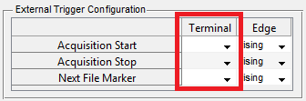
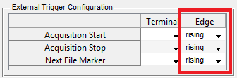
External Trigger Configuration
|
Assign a role to an external trigger. See Acquisition Triggering for a description of each role. This is the physical terminal to which your trigger signal is attached. Icon Each physical terminal can be connected to one or more trigger functions. |
|
Configure the input terminal to expect either a rising or falling TTL transition. The edge on which the trigger signal generates the selected trigger function. Icon A trigger function can be assigned to the rising edge and falling edges of a single physical terminal. |
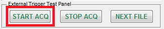
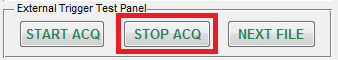
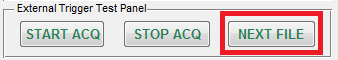
External Trigger Test Panel
|
Generates an “Acquisition Start” trigger signal. |
|
Generates an “Acquisition Stop” trigger signal. |
|
Generates a “Next File Marker” trigger signal. |
Note
The External Trigger Test Panel buttons can only be used if External Triggering is enabled in the Main Controls Window.
Tip
You can use the External Trigger Test Panel to test your scanimage configuration without having to actually generate external hardware test signals.