Period Trigger

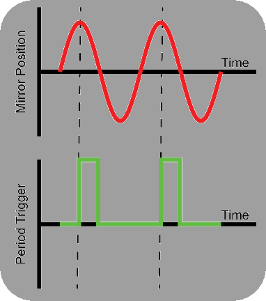
The period trigger signals a constant phase of the resonant scan period.
Note
If operating a version of ScanImage® preceding ScanImage® 2019, the period trigger must always be wired to PFI0 of the resonant scanning auxiliary DAQ.
In the current version, this is a user configurable port
Description
Supported resonant scanners are supplied with a controller that exports a timing signal called the Period Clock (or SYNC or Trigger).
The period clock is (ideally) a TTL pulse that transitions from low to high at a precise phase of the resonant mirror’s scan motion. It is one of the most important timing inputs for the microscope.

Each period trigger initiates the acquisition of two lines in the image.
Relationship to Image Formation
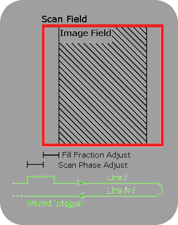
Each period trigger signals the digitizer to acquire data from a bidirectional scan. The digitizer’s online processing then formats this into two lines in the image and resamples so that output pixels represent equal intervals of space at the desired resolution.
The very edges of the resonant mirror’s scan field are discarded (see the Fill Fraction controls in the Configuration Panel); typically the laser power is attenuated in this region to prevent the sample from burning. For more information on the Fill Fraction see Fill Fraction.
By default, the period trigger may not be precisely aligned to the edge of the scan field. The Scan Phase can be adjusted in the Configuration Controls. For more on adjusting the scan phase see Scan Phase.