Volume Imaging
A ScanImage Stack acquisition is composed of multiple sub-acquisitions termed Slices, each identical but obtained at one of a set of evenly spaced axial (Z) positions of the motor. There are two options to choose between, Slow and Fast. All Stacks are defined by the following basic parameters:
Number of Slices - These indicate the quantity of unique Z planes, or slices, you wish to image at.*
Frames per Slice - The number of individual frames to acquire at each slice.**
Number of Volumes - This indicates the number of times, if any, that the stack, or single volume, should be repetitively acquired.***
Step Size (um) - This indicates the displacement in um of the Z axis, and thus the focal point, between each slice.
A stack acquisition can only be enabled via data collecting acquisition mode - i.e. a single GRAB acquistion or LOOP Repeat. Using FOCUS will only collect images at the current Z plane regardless of volume/stack settings.
Note
Compatibility
This page is accurate for SI 2019 and beyond. Previous versions may differ slightly as explained
* Setting the number of slices above 1 automatically makes the acquisition a volume/stack acquisition. In SI 2019 you must enable stack mode before being able to change this value.
** In older versions when doing Fast volumes/stacks the value may not exceed 1 frame per slice or Z plane.
*** In older versions only Fast volumes/Stacks supported repeated volumes.
Note
Tiff File Structure
A stack is saved as a TIF file with each slice consecutively stored in the file, from first to last. If there are multiple frames/slice, then all frames for a given slice are written first before writing the next slice’s frames.
Slow Volumes/Stacks
Slow Stack acquisitions utilize a motorized stage to make steps in the axial (Z) direction (typically along the microscope objective). Stages can be configured in the Resource Configuration via the Stage Controllers (Motors) page and must define a Z axis.
Slow Stacks are named as such for two primary reasons
They utilize serial controlled motorized stages to command incremental movements to make steps. After a step is commanded there is a routine in place to wait for the device to respond and move to the desired position and to verify the position prior to the start of the next slice.
Acquisition routine is explicitly comprise of multiple separate sub acquisitions with a process as follows
Move to start position
Verify position
Acquire N frames
Verify Acquisition done
Verify number of Z planes completed
Move by step amount to next Z plane
Repeat 2-7 until all Z planes are imaged.
As such entire pipeline can be timely especially and is dependent and the speed and reliability of the stage in use.
Warning
Stage Failure To Move
In order to avoid possible complications from a serial commands to a stage not being received or responded to there is pipeline built into our motors system to verify whether the stage is or is not moving as well as a time limitation for the completion of a move for situations where the stage may be moving but due to some issue it is not moving correctly. If the motor fails to respond or takes too long to move, the stack acquisition will be aborted and an error will be thrown.
Note
Triggering
Due to the way Slow Stacks work, not all triggering options are available.
Note
Slow Stack with Fast Z
When taking Slow Stacks you will have the option to select a movement device as either the motors, or the FastZ device. The difference is that in Slow Stack mode rather than using a buffered waveform, the same incremental routine is used however, when moving to the next Z plane instead of writing a serial command to step the stage we just write a discrete voltage value corresponding to the next slice position.
Fast Volumes/Stacks
Fast Stack acquisitions are performed via control of continuous (non-stepping) axial motion device synchronized to an uninterrupted stream of acquired image frames. Such ‘Fast Z’ Image Stacks are distinct from standard (‘Slow Z’) Image Stacks which use discrete axial steps for each separate set of one or more image frames.
Fast Stacks utilize a hardware timed buffered AO waveform to drive an analog positioning device. Generally a Piezo PiFoc (piezoelectric actuators) or remote focusing mirror. Such devices are configured in the Resource Configuration window via the Fast Focus page page.
Fast Stacks are named as such because:
The devices themselves are quick reacting analog driven devices
The devices are controlled by a hardware timed streaming analog waveform
Waveform and Buffer
In a Fast Stack the Z device is constantly moving through the Z planes with its speed determined by the number of samples in the AO buffer and the resolution of those samples.
Since the AO Sample Rate (samples per sec) of the driving DAQ card as well as the voltage to um relation of the device are known to us, the speed of the scanner and the position in Z at a given point in time are deterministic. As such the controlling waveform is synced with acquisition so that each frame is acquired when the device has move by roughly the step size.
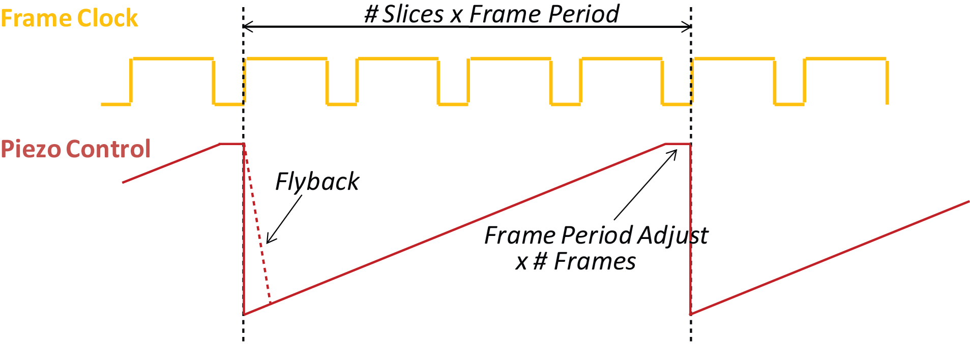
The control AO is a continuous axial trajectory waveform/command of duration slightly shorter than (N * FP), where N is the number of slices in the Fast Z Image Stack and FP is the known (measured) frame period at the current scan settings. Each volume period waveform is initiated by a frame trigger signal from the scanner system. The waveform is kept slightly shorter than (N * FP), to ensure the waveform is re-started by the very next frame trigger following the volume sweep.
Waveform Types
There are two waveform types supported by Fast Stacks, the first is a sawtooth waveform as seen above. The second is a stepped waveform.
In the case of a stepped waveform the AO waveform will hold the same value for length of time equal to a frame period and use the inter frame time, or frame flyback time, to ramp to the next AO level. Each level equates, via voltage to um conversion, the next Z plane in the stack.
Note
Frame Averaging
Since the sawtooth waveform means that the device is constantly moving, the device will only be at a specified Z plane for 1 frame period. Thus multiple frames can’t be acquired at the same Z plane and no frame averaging can occur. However, the step waveform will allow you to expand the amount of time spent at the same voltage value and thus the same Z plane. Therefore in step mode you can acquire multiple frames per slice and can then perform averaging as needed.
Please see the Stack Controls Window for more information on configuring volume imaging.