Configuration Tutorial
This tutorial will describe the configuration of a single path microscope using a simulated vDAQ and RMR scanner. Following this 15 minute tutorial will give perspective on how to set up a microscope, how to find which devices are compatible with ScanImage, and give the ability to explore ScanImage® features.
Requirements - A PC, Matlab installation, ScanImage® license, power cable, internet connection, monitor, mouse, and keyboard are required to follow this tutorial.
1. Set up the computer
Follow the steps in PC Configuration to install ScanImage on your computer.
Note
Labs with an active MBF Assure plan can install ScanImage from a Git-based release repository rather than a static download. The release repository enables automatic update notifications at ScanImage startup, one-command switching between any historical ScanImage version, incremental bugfix updates, and lab-specific customization workflows. See Release Repositories for details.
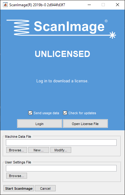
Start up Matlab, type the command
>> scanimage
into the Matlab command window, and press enter. This will bring up the launch window. From the launch window, the ScanImage® installation can be licensed by clicking the Log In button, logging in with your Vidrio Tech site login and then selecting the Download License button. You will be able to select from multiple licenses if multiple licenses were purchased - ScanImage® licenses are typically single-seat licenses.
License Management (SI2022+) provides additional information about ScanImage’s license system.
2. Select Microscope Type
Click New… under the machine configuration panel in the launch window and save the machine configuration .m file to reveal the New Microscope Configuration window.
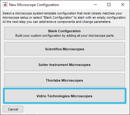
This window provides templates for several microscope vendors. For this example, Vidrio Technologies Microscopes is used.
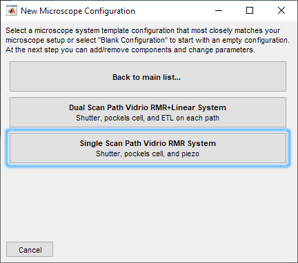
This reveals two options utilizing the Vidrio Rapid Multi Region Scanner - a Dual Scan Path Vidrio RMR System + Linear System and a Single Scan Path Vidrio RMR System. There is a brief listing of used devices under each option. Here, a Single Scan Path Vidrio RMR System is selected.
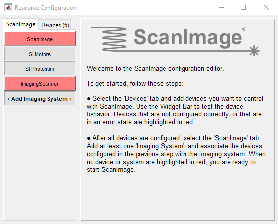
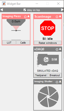
Selection reveals the Resource Configuration window and the Widget Bar
|
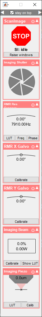
|
3. Configure Devices
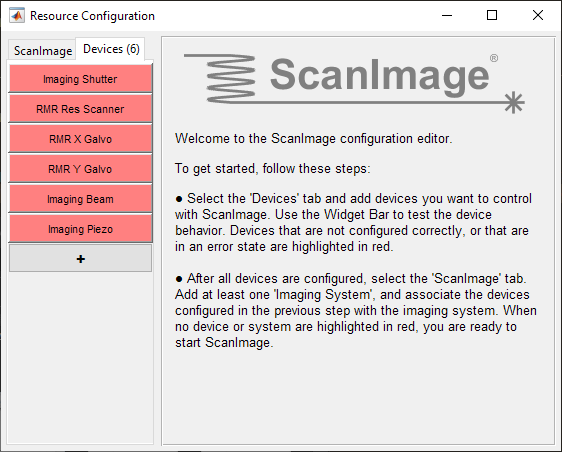
The Resource Configuration window is divided into two tabs - ScanImage and Devices.
Devices are optical components that are controlled by ScanImage (galvos, stages, shutters etc.)
These devices are combined together into imaging systems under the ScanImage tab
For example, the ImagingScanner component is comprised of a resonant scanner, X and Y galvanometric scanners, beam modulators, shutters, and a fast focus device.
Notice that each of the devices in the Widget Bar and ScanImage® components in the Resource Configuration window are highlighted red. This is an indication that the devices are in an error state. Each device needs to be configured before use.
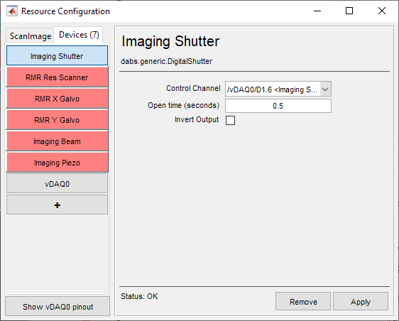
Select the Devices tab from the Resource Configuration window to reveal the device configuration pages. You can select the device to be configured from the sidebar on the left. Alternatively, if ScanImage® was already launched and the Resource Configuration window is not open, clicking the cog in the top right of any device’s widget from the Widget Bar will summon the Resource Configuration and display that device’s configuration page. The Imaging Shutter is selected.
|
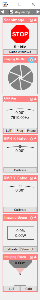
|
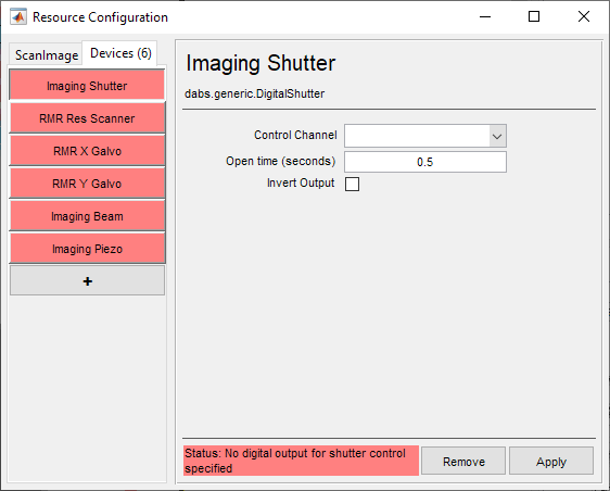
The Imaging Shutter has three configuration settings - Control Channel, Open Time (seconds), and Invert Output. Open Time (seconds), and Invert Output can be configured, however there is no DAQ installed to configure the Control Channel.
Note
Text with red highlight at the bottom of the Resource Configuration window specifies why a device is not configured correctly.
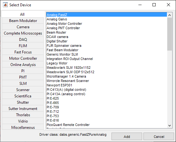
To add a simulated vDAQ, select the + button in the Resource Configuration window’s sidebar. This will reveal the Select Device window. This window lists all devices that are supported in ScanImage®.
Several device drivers are generic and can be used with a wide variety of makes and models. These include Beam Modulators, Shutters, and Scanners.
Some devices are composed of other devices, i.e. the Vidrio RMR is composed of one Resonant Scanner device and two Analog Galvo devices. These composite devices include predefined parameters for their included devices which are specific to their models; for instance, the RMR Y Galvo device differs from a Sutter Y-Galvo by Volts per optical degree, Angular Range, and Park Position.
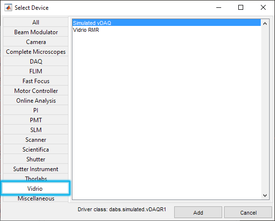
Go to the Vidrio tab, and select the Simulated vDAQ device.
|
|
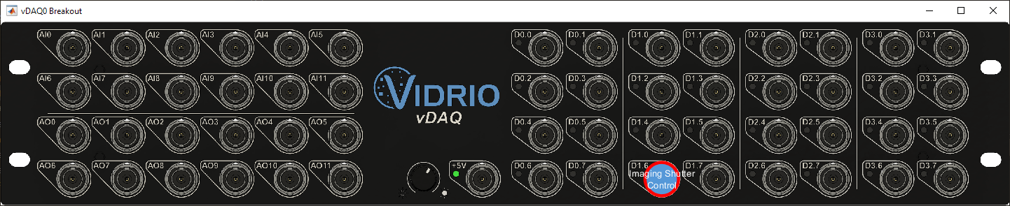
This will add the vDAQ as a device. It will be referred to as vDAQ0 in other device configuration pages. A widget for it is also added into the Widget Bar. When you click the Breakout button in its widget, a window with a breakout box is displayed. This window will label assigned ports as you configure devices to provide an overview when referencing connections. For example, after assigning port /vDAQ0/D1.6 to the Imaging Shutter, the window reflects this assignment as shown. Note that the device in the Resource Configuration sidebar and Widget Bar turn gray to show that the device is no longer in an error state and ready for use with ScanImage.
|
|
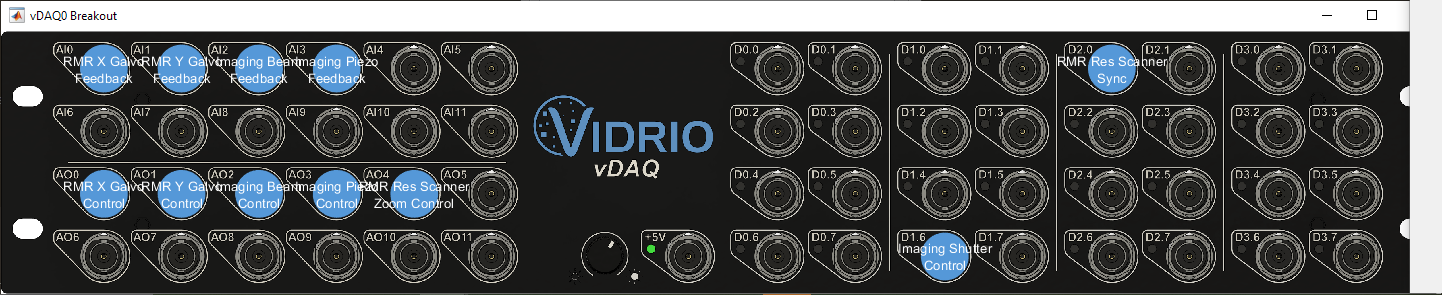
Continuing with assigning ports and setting parameters, a complete device configuration for this microscope may look like shown:
4. Configure ScanImage® Components
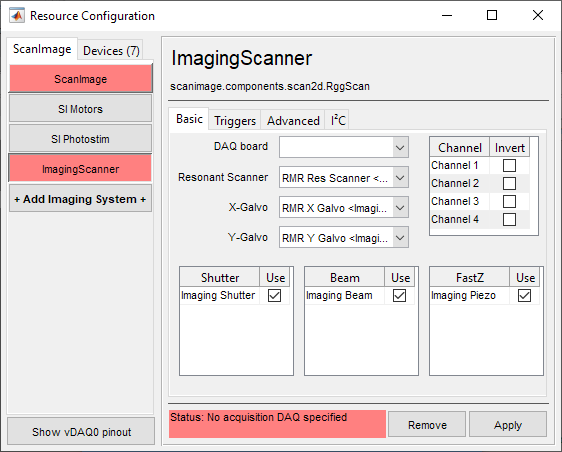
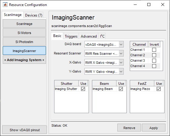
After all devices of the microscope are configured, Imaging Systems can be configured by selecting the ScanImage tab of the Resource Configuration window. Select the ImagingScanner from the sidebar. The highlighted text at the bottom of the window indicates “no acquisition DAQ specified”. Select the simulated vDAQ0 as the DAQ board and select Apply. The scanners, shutter, and beam modulator for the imaging scanner of the Single Scan Path Vidrio RMR System have been pre-configured.
|
|
The ImagingScanner subsystem is in an error state (“No acquisition DAQ specified”). ScanImage will not be able to start (as indicated by the red background of the “ScanImage” button) |
All ScanImage subsystems are configured correctly. ScanImage is now ready to be launched. |
Ensure that no device or ScanImage component is highlighted in red. If no device or ScanImage® component is in an error state, ScanImage® is ready to be launched. Close the Resource Configuration window and click Start ScanImage on the launch window. Once ScanImage® is initialized, all of the GUI windows will appear at once. Tutorials can now be followed using simulated hardware. See the Acquisitions page to try an acquisition.