Motorized Half-Wave Plate
A motorized half-wave plate can modulate beam power via rotation of a half wave plate and a downstream polarizing beamsplitter. See Thorlabs’ tutorial on half-wave plates. The driver requires at a rotation stage to be configured as a motor controller device. Optionally, a photodiode can be assigned for use with this half wave plate to calibrate output power to vary linearly with user controls.
A motorized half-wave plate can be used during simple raster-pattern acquisitions (without beam blanking) and also slow stacks with power versus depth adjustment profiles. Outside of an acquisitions, the beam power can be modulated via the widget by clicking and dragging in the power fraction rectangle.
It is not suited for multiple regions of interest (MROI) scanning where there are varying powers per ROI, or line scanning with varying powers per stim function. It cannot do power boxing nor power versus depth adjustment for fast stacks.
Hardware
Use any rotation stage that is compatible with a motor controller driver. Below are examples of compatible stages and their motor controller drivers.
Motor |
ScanImage Driver |
Thorlabs PRM1Z8 |
|
Scientifica Rotation Stage |
|
Follow setup steps outlined in those pages and return here
It is also desirable to be able to calibrate output power. To learn about optical setup with a photodiode, visit the Optical setup section of our Fast Beam page. Connect the Photodiode to any free analog input.
Note
To successfully detect the true depth-of-modulation of the Pockels Cell, it is important that the photodiode gain is appropriately set, so that it has sufficient signal at the low end, but also does not saturate at the high-end. Incorrect photodiode gain is a common source of Pockels calibration errors.
ScanImage Configuration
Prerequisites: The rotation stage and optional Digital Shutter to be opened during calibration must already have been configured.
In ScanImage, open the Resource configuration window from the startup dialog or from the Main Controls window under File>Configuration.
From the Resource Configuration window, click the “+” button. Select Beam Modulators from the sidebar, and select “Motorized Half Wave Plate”. Give it a name and continue.
A window like shown below will be displayed. Below the image is a description of each of the configuration parameters
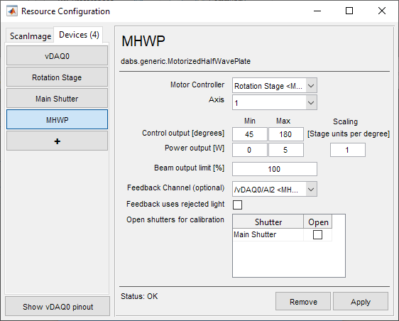
Motor Controller |
Select the rotation stage from the dropdown of all configured motor controller devices. |
Axis |
Many motor controllers have several enumerated axes for XYZ translation and/or rotation, designate the axis responsible for rotation of the Half Wave Plate. If this is a single axis controller, select the only axis available. |
Output Range |
This is the lower and upper bounds of travel of the rotational stage in degrees. Some stages internally keep track of “rollover”, so any commands past 360 degrees will be report positions back as a modulus of 360 degrees in stage units. Some controllers may not do this. Some controllers may refuse rollover at all. Within the span of 360 degrees are four spans of angles that increase from minimum power to maximum power while rotating in one direction. In the interest of being universally compatible, the output range has been set to receive numbers no less than 0 degrees and no greater than 360 degrees. One could just assign a large enough angle range in degrees and the calibration with photodiode will find an appropriate, continuous sub-range of angles to find the minimum and maximum power. Note Rotating a half-wave plate a full rotation should yield four cycles of modulating the power from the minimum to maximum power. Thus, one should find a range of angles sweeping from minimum to maximum power within a 135 degree range from any starting point: 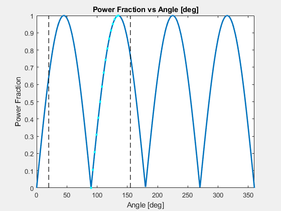
If a calibration cannot be done every time ScanImage is launched, the user can do a single calibration and save the look up table as a .beamlut file. If a calibration cannot be done at all, one can guess positions for minimum and maximum power and use a naive, linear correlation between modulation angle and beam power. |
Scaling [Stage units per degree] |
This is the conversion factor from degrees to device units for the stage. For some controllers, the stage units are already in degrees, so the conversion can be set to 1. For other stages, encoder ticks or steps are counted with a certain number of ticks or steps per rotation. This can usually be found in a stage/stage controller’s documentation. |
Power Output [W] |
This is the expected minimum and maximum power in Watts of the modulated beam. |
Beam output limit [%] |
This is an arbitrary percent of maximum laser power to set an upper bound on what laser powers the user can use. |
Feedback Channel |
This is the DAQ analog input channel from where a photodiode can be connected to calibrate laser power with the angle of the half-wave plate in degrees |
Feedback uses rejected light |
This is a true (checked) or false (unchecked) parameter that tells ScanImage to interpret the feedback photodiode signal differently depending on whether laser power at the sample is proportional (not using rejected light) or inversely proportional (using rejected light) to the power measured from the photodiode. |
Open shutters for calibration |
If the motorized half-wave plate is set downstream of ScanImage® configured shutters, then select those shutters to be opened for calibration. Note It is recommended to have laser continuously passing through the half-wave plate uninterrupted by shutters to eliminate any transient effects of that come from intermittent irradiation. This can ensure that the calibration curve and laser power at the sample remain the same throughout an experiment (given sufficient warm-up time). |
Once finished configuring the motorized half-wave plate, select Apply.
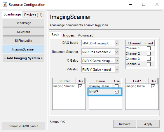
3. In order to use the configured device, select the ScanImage tab. Under page of the imaging system which should use the motorized half-wave plate, place a check next to its name in the Beams table.