Line Formation
The scan angle of a resonant scanner over time follows a sinusoidal pattern, so that the angular velocity of the scanner is greatest at 0° deflection, while the angular velocity is 0 at the maximum deflection. If the non-uniform angular velocity of the scanner is ignored during image formation, the resulting image is warped in x. To form pixels, ScanImage® averages multiple digitizer samples using a FPGA. Since the digitizer samples at a constant rate, a varying number of samples needs to be used for each pixel to correct for the non-uniform angular velocity of the scanner. ScanImage® calculates a sample to pixel mask at the start of an acquisition and stores it on the FPGA. The FPGA then applies the mask to the incoming data stream from the digitizer to form a line.
Since more samples are averaged at the edges of the field of view and the edge of the field of view is scanned slower than the center, the signal to noise ratio varies over the field of view. This can easily be observed by imaging a uniform sample such as a fluorescent slide: The center of the field of view (in x) will show a higher SNR then the edges of the field of view.
Note
The calculation of the sample to pixel mask depends on the pixels per line, Spatial Fill Fraction <Fill Fraction>, digitizer sample rate and resonant scanner frequency. From these parameters, only the resonant scanner frequency is not known with high accuracy. Since the resonant scanning frequency can drift over time due to changes in temperature and the amplitude of the scanner, it is advised to measure the frequency before every acquisition. In ScanImage, this can be achieved by selecting the ‘Measure’ button in the Configuration Controls.
Note
In ScanImage, the mask is stored in the variable hSI.hScan2D.hAcq.mask In bidirectional mode, there are two parts to the mask: one forward line and one backward line, separated by a negative wait count in the middle.
Inspect the function scanimage.util.computeMask to see the algorithm used to compute the mask.
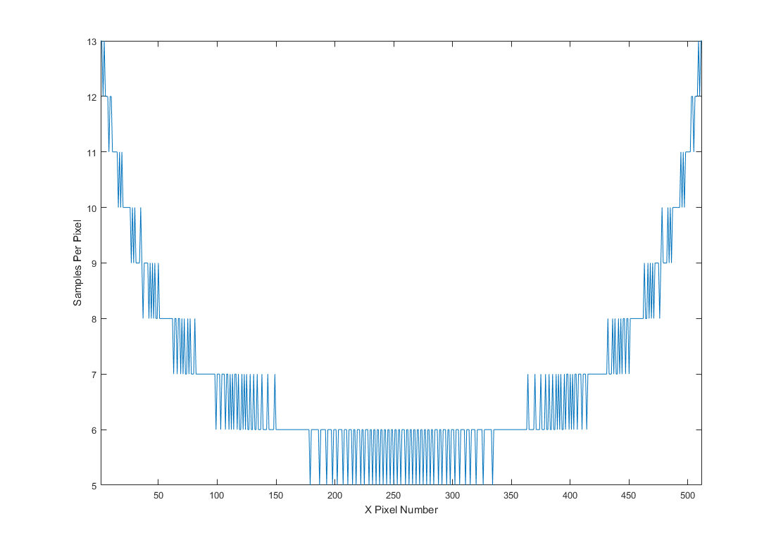
Typical mask used in ScanImage
Mask used by ScanImage® for a typical acquisition (pixels per line: 512, spatial fillfraction: 0.9, resonant frequency: 7910Hz, 80MHz sample rate)
Note
ScanImage® can be configured to bypass the mask and instead use a constant number of digitizer samples per pixel. This can be configured by the following commands:
hSI.hScan2D.uniformSampling = true; % use a constant number of digitizer samples per pixel instead of applying the mask
hSI.hScan2D.pixelBinFactor = 1; % define the number of digitizer samples used to form a pixel
Note
Since more samples are averaged at the edges of the field of view and the edge of the field of view is scanned slower than the center, the signal to noise ratio varies over the field of view. This can easily be observed by imaging a uniform sample such as a fluorescent slide: The edges of the field of view (in resonant scan axis) will show a higher SNR than the center of the field of view.
Sample to Pixel Assignment
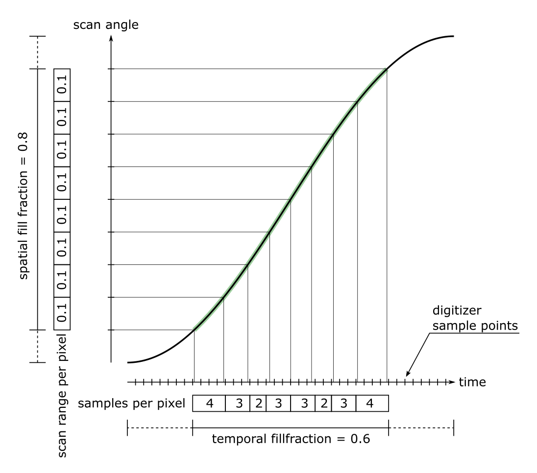
Example of samples to pixel assignment for a line with 8 pixels, and a spatial fillfraction of 0.8. The part of the scan used for image formation is highlighted in green.
To achieve a uniform scan angle per pixel, a varying number of digitizer samples are used to form the pixels. Note that the assignment is imperfect because of quantization errors.
In ScanImage, this sample to pixel mask is calculated for every acquisition, and applied to the input data stream on the FPGA. A pixel is formed by calculating the arithmetic mean of the number of samples specified in the sample to pixel mask. Note: because the algorithm is implemented on an FPGA, the mean uses integer division.