Beams
Intensity modulation of the ultrafast lasers typically used for two-photon imaging is typically done using a Pockels Cell.
The laser intensity is modulated to control
The laser power during an exposure.
Beam blanking on the left and right edges of the frame.
Beam blanking between image frames during the Y mirror flyback.
ScanImage® allows control of multiple Pockels Cells (or other similar light modulators). The command signals generated by ScanImage® for control of these devices are termed Beams. These signals can be controlled by ScanImage® in several contexts:
Simple static control of power level to use during acquisitions. This avoids need for simple manual control of a laser attenuator. See the Power Controls Window.
Dynamic control of power during each scanned Line, blanking the Beam during the non-acquiring portion of each Line Period. See Line Formation.
Control and Timing
The beams are controlled by a signal generated by the FPGA called a Beam Modified Line Clock.
GUI
See Power Controls.
Calibration
Calibration is the process for establishing an accurate relation between power fractions specified from the beam controls gui and the actual fraction of laser power post beam modulator.
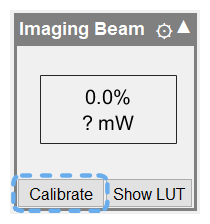
To calibrate a fast beam modulator or motorized half-wave plate, click on the calibrate button in the widget of the beam that you would like to calibrate.
Data Collection
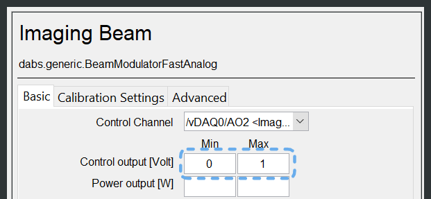
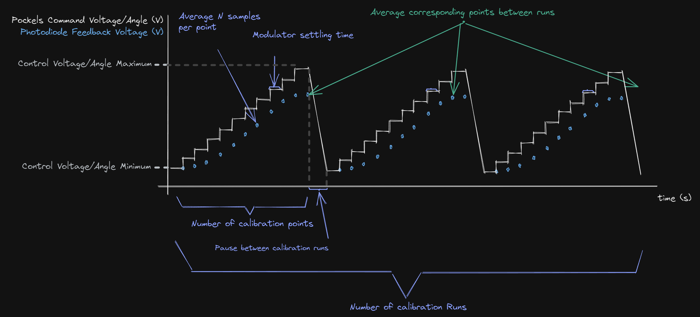
Calibration for each Beam consists of sweeping a series of voltages increasing from
the minimum to maximum control voltage range specified in the in the Beam Modulators Resource Configuration Page.
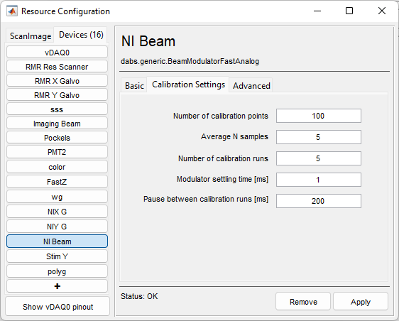
Some calibration settings are offered so that the best balance of power look up table precision and practicality of calibration can be decided by you, the user. Text items in purple are settings that can be altered in the Calibration Settings tab of the configuration page.
Note
The beam output limit will be ignored for calibration.
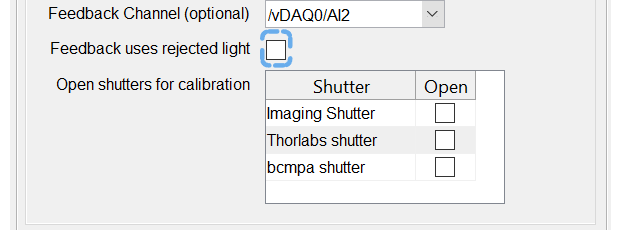
Simultaneously, samples are collected for each control voltage point from the configured analog input connected to the photodiode. The photodiode can receive either the rejected or the in-line light for calibration as depicted in the below side-by-side figures.
In-line |
Rejected |

|

|
While it is discouraged, a shutter can be placed between the laser and the beam modulator, in which case you would want to open the shutter when calibrating. If this is the case, you place a check in the box of such shutters.
Note
The Pockels Cell power modulation is temperature dependent. If the microscope’s main shutter is placed before the Pockels Cell, the cell heats up while the shutter is open and cools down when the microscope is inactive and the shutter is closed. To ensure the Pockels Cell is remains in thermal equilibrium, the shutter should be located after the Pockels Cell.
Data Processing
Going from the Calibration settings tab, Quantity Average number of samples
are averaged together at each point to or each of the Number of calibration points.
Then, points are averaged with corresponding points from each calibration run (Number of calibration runs)
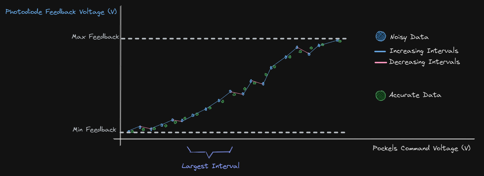
to form one averaged run of data (see image below). A successful calibration produces a curve that is smooth and non-saturated.
From this calibration, we find the largest monotonically increasing or decreasing contiguous sequence of voltages. The largest monotonically rising or falling interval in the run will be used for creating the beam power look up table, but it must pass some validation criteria:
The highest collected value in the interval must be within 1% of the range from the highest feedback value collected for the whole run
The lowest collected value in the interval must be within 1% of the range from the lowest feedback value collected for the whole run
- To see how this is implemented or change it to your liking, see file +dabs/+generic/BeamModulatorFastAnalog.m in functions:
calibrate
processCalibrationData
More considerations
Below are some important considerations when doing a calibration
Dynamic Range
Ratio of the maximum to the minimum signal level measured during Beam Calibration determines the dynamic range of the Beam. The minimum value allowed for the Power level is clamped accordingly, e.g. 0.1% implies a 1000:1 dynamic range, 0.5% implies a 200:1 dynamic range, etc.
Note
To successfully detect the true depth-of-modulation of the Pockels Cell, it is important that the photodiode gain is appropriately set, so that it has sufficient signal at the low end, but also does not saturate at the high-end. Incorrect photodiode gain is a common source of Pockels calibration errors.
Accuracy
ScanImage® internally regards the power level used as a percentage of the maximum measured power. It is possible to display/enter power levels in power units directly (e.g. milliwatts), by measuring and specifying a power in the beam modulator’s resource page.
For some light modulators (e.g. Pockels Cells), the calibration relationship between voltage and percent-power depends on the laser wavelength. In such cases, the calibration should be updated when the laser is significantly re-tuned. If often switching between laser wavelengths, it may be beneficial to run a calibration at each wavelength, save LUTs, and load them accordingly.
Overcoming Anomalies
If the SNR of the collection is too low, then this may cause the averaged run to be broken up into several smaller monotonically rising or falling intervals whose min and max values are not within 1% of the max and min overall. If you are experiencing this, you can cope by
increasing the number of runs
increasing the number of samples collected per point
If this alone does not help, it may be helpful to decrease the number of points per run, although this will make the calibration more coarse. It may be better to check a few basic things first:
Ensure the photodiode is powered on and responds to incoming light
Check that the beam modulator is turned on.
Check that the calibration beam is making it to the photodiode (Is the laser shutter open? Is the laser on? is the laser pointed at the photodiode sensor?)
If applicable, is the photodiode gain set to provide a reasonable voltage difference between the minimum and maximum modulated laser power?