Vidrio RMR
The Vidrio Rapid Multi Region (RMR) Scanhead contains an x-axis resonant scanner, a ScannerMax Saturn-5 x-axis galvo scanner, and a ScannerMax Saturn-5 y-axis galvo scanner. This scanner configuration enables the microscope to perform Multiple Region of Interest scanning
Optical Configuration
The Vidrio RMR is compatible with the Thorlabs Bergamo Scope 2 and the Sutter MOM and is also well suited for DIY microscopes.
Tip
Contact Vidrio Sales to inquire about professional installation services.
Thorlabs Bergamo Scope 2
When the RMR scanner is ordered with the BScope installation kit, the following items are included:
4x Clipped Washers (McMaster PN: 96025a124)
4x 4-40 Screws 1/4” long ([McMaster PN: 92196a106)
4x 1/4” Cage Rods (Thorlabs ER025)
BScope 2 Lens Adapter supplied by Vidrio
Attention
Exercise extreme caution during installation. Vidrio is not liable for damages incurred from improper installation.
Fasten the 1/4” cage rods to the exit port. Next, thread the BScope 2 Lens adapter into the RMR beam exit port.
Insert the BScope 2 Lens adapter into the scope as shown and fasten the 4x 4-40 screws with clipped washers into the cage rods to fix the RMR in place.
A periscope should be mounted to the RMR beam input such that it does not hinder the microscopes intended range of motion while steering the laser to the input port.
Sutter MOM
Vidrio offers a periscope for bringing the laser from the optical able to the RMR scanner.
When the RMR scanner is ordered with the Sutter installation kit, the following items are included: - 3x Shoulder Screw ⌀4mm, 5mm shoulder length.
Attention
Exercise extreme caution during installation. Vidrio is not liable for damages incurred from improper installation.
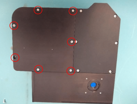
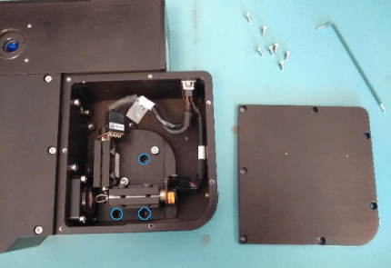
Remove the plate covering the galvo compartment of the RMR using an H2 allen key.
Attention
Be careful not to strip the screw heads!
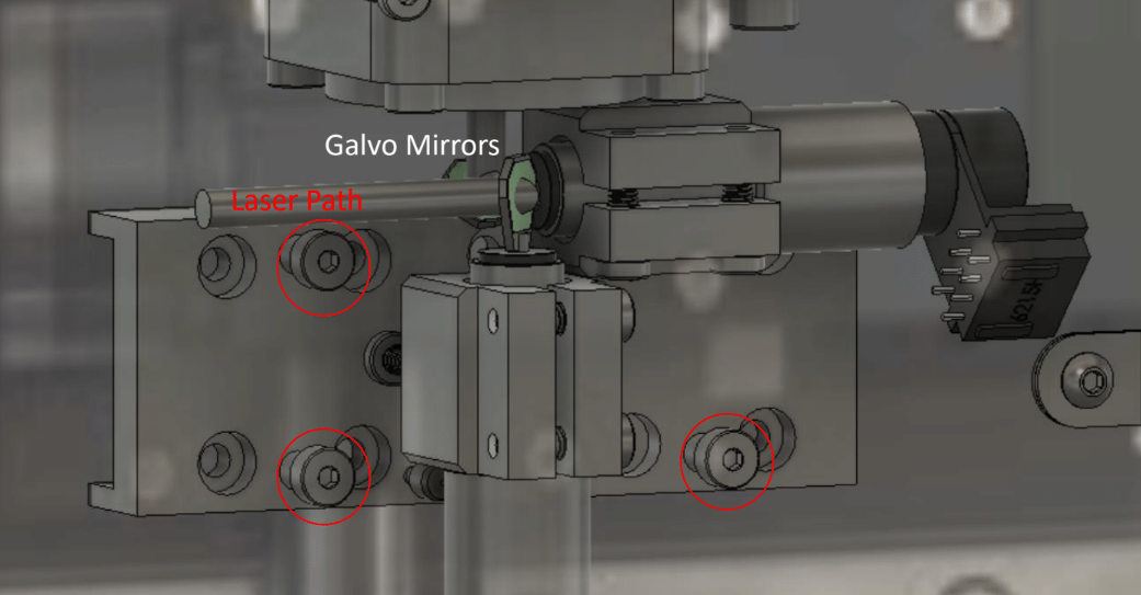
Use provided M3 shoulder screws to fasten the RMR to the Sutter sled. While holding the RMR scanner up to the sled align the three highlighted RMR holes with the sled mounting holes
Attention
Use extreme care while attaching the screw near the galvo mirrors.
|
|
Affix other optical components to direct the beam into the beam entrance port of the RMR. Vidrio sells a periscope separately that may be useful.
DIY Mounting
Vidrio sells separately an adapter plate that will allow the user to thread Thorlabs 1/2” optical posts to the bottom of the RMR so that it can be supported from underneath.
All that is required is to fasten the adapter to the RMR via 4x M4 screws.
Hardware Configuration
Note
make note of DAQ ports connected to controller ports for later ScanImage® configuration
Connect the galvo cable (26-P D-Sub, Male-Male) and resonant cable (15-P D-Sub, Male-Male, also known as a VGA cable) between the RMR controller and the RMR scanhead.
If using a vDAQ:
X-Galvo
Choose a free analog output channel to connect to the controller X-Galvo position command input via BNC cable.
Choose a free analog input channel to connect to the controller Y-Galvo position feedback output via BNC cable.
Y-Galvo
Choose a free analog output channel to connect to the controller X-Galvo position command input via BNC cable.
Choose a free analog input channel to connect to the controller Y-Galvo position feedback output via BNC cable.
Resonant Scanner - Choose a free analog output channel to connect to the controller Zoom input via BNC cable. - Choose a free digital input channel to connect to the controller Synchronization output via BNC cable.
Optionally, enable channel can be connected for enabling/disabling the resonant scanner. Connect it to a free digital output.
Otherwise, if using an NI DAQ:
Start fresh with a DAQ that hasn’t had any any connections made yet.
X-Galvo
Choose a free analog output channel to connect to the controller X-Galvo position command input via BNC cable.
Choose a free analog input channel to connect to the controller Y-Galvo position feedback output via BNC cable.
Y-Galvo
On the same DAQ as the X-Galvo:
Choose a free analog output channel to connect to the controller X-Galvo position command input via BNC cable.
Choose a free analog input channel to connect to the controller Y-Galvo position feedback output via BNC cable.
Resonant Scanner
On another DAQ without preexisting connections:
Choose a free analog output channel to connect to the controller position command input.
Connect the controller’s resonant sync signal to a user port and bridge a PFIx terminal to the User # terminal using hookup wire.
Optionally, the enable channel can be connected for enabling/disabling the resonant scanner. Connect it to another User input and bridge a PFIx terminal to the User terminal # using hookup wire.
The controller may be connected to power and turned on.
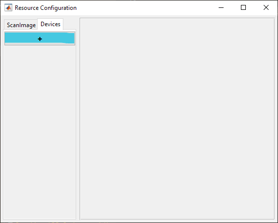
ScanImage® Configuration
From the Resource Configuration window, under the Devices tab click the add device “+” button.
Select Scanner from the sidebar and then Vidrio RMR and click Add. Assign it a name and click OK. This creates 3 devices:
Vidrio RMR Resonant Scanner
Vidrio RMR X-Galvo
Vidrio RMR Y-Galvo
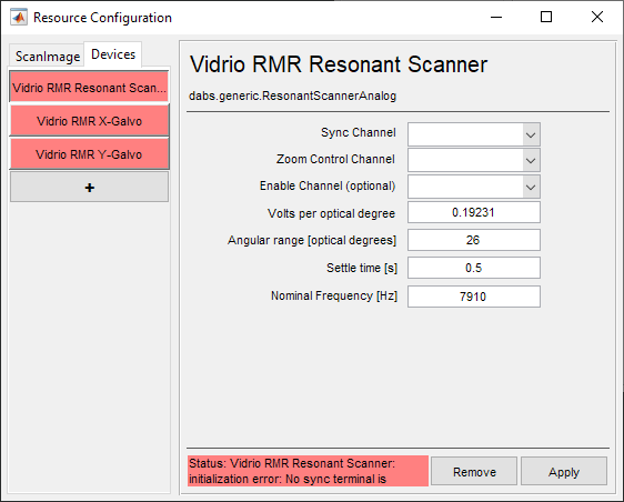
These are Resonant Scanner and Analog Galvo device drivers which have been pre-configured for the models of resonant and galvo scanners inside the RMR. All that is required is to specify the DAQ ports that were connected during Hardware Configuration.
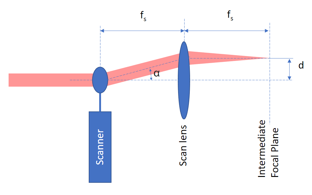
Field of View Calculation
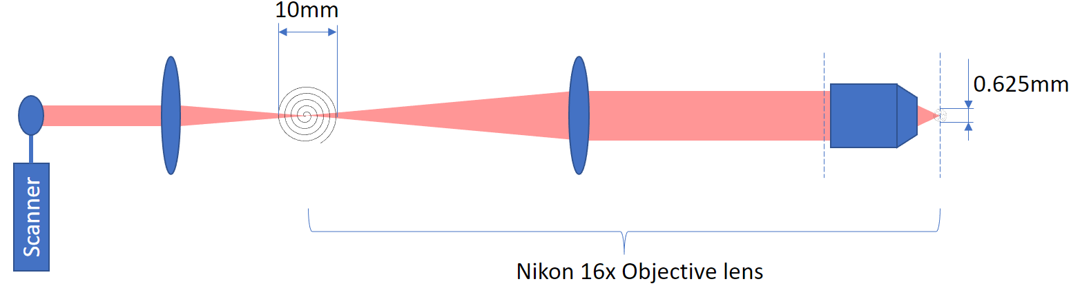
The RMR FOV is directly dependent on the lateral deflection in the intermediate image plane. This deflection d is defined by the scan angle α and the focal length f_s of the scan lens through the formula: d = f_s * sin(α)
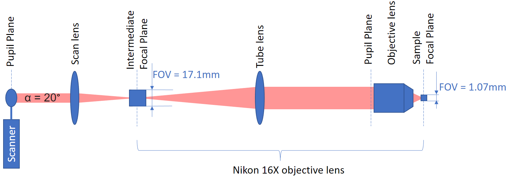
Let’s consider a basic example with typical lenses
Thorlabs SL50-2P2 scan lens with a focal length fs = 50 mm
Nikon objective lens with magnification** M = 16
The RMR scanner has a scan angle range of α = +/-10 degrees for a total range of 20 degrees.
Intermediate focal plane:
FOVi = d = sin(20) * 50mm = 17.1mmFocal plane:
FOV = FOVi / M = 17.1mm / 16 = 1.0688mm
Tip
The objective magnification** depends on the focal length f_t of the tube lens and the focal length f_o of the objective. M = f_t / f_o. The above Nikon objective uses a tube lens with focal length of 200 mm and an objective focal length of 12.5 mm to give a magnification of 16x. Note that the image at the sample is 16x smaller.