vDAQ Configuration
ScanImage® supports vDAQ for data acquisition and microscope control. vDAQ is an all-in-one controller for the most advanced laser scanning microscopes.
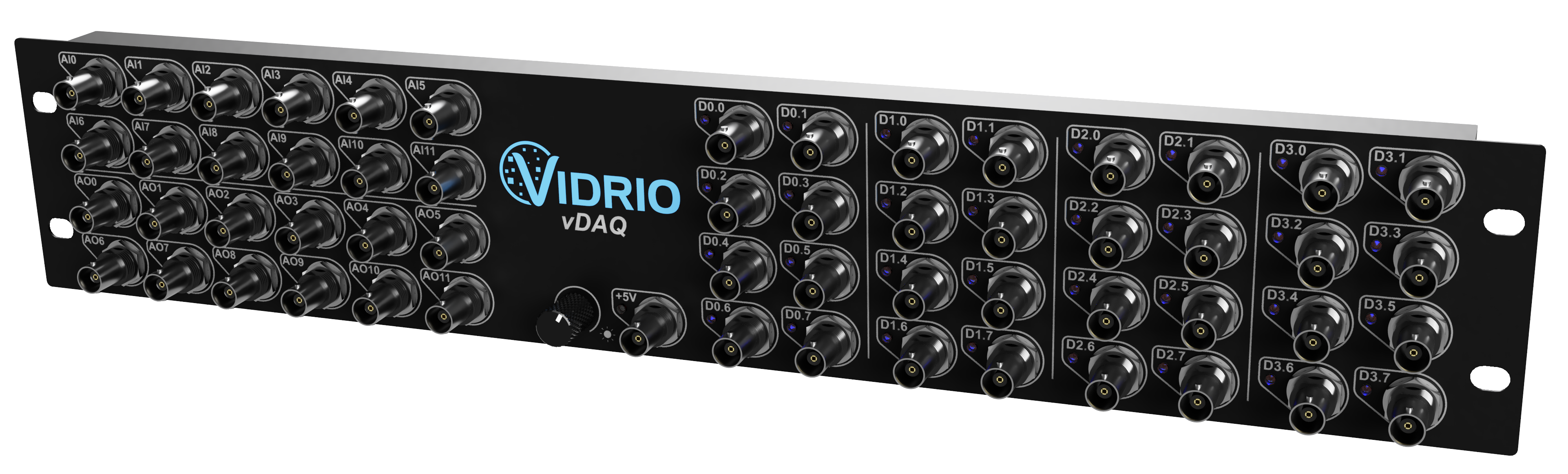
The 2U rackmountable vDAQ breakout shows the main functionality of the data acquisition system:
4 fast analog inputs for acquiring PMT data
12 2MHz analog outputs for microscope control (Galvos, Piezos, Pockels Cells, …)
12 1MHz analog inputs for actuator feedback
32 digital inputs/outputs for triggering / clocking
Setup
After installing vDAQ in the computer, one can simply assign AO, AI, DO, and DI ports to devices within scanimage’s resource configuration window within individual Device configuration pages.
Simulated vDAQ Setup
For evaluation purposes, ScanImage can be configured to use a simulated vDAQ by following the below instructions:
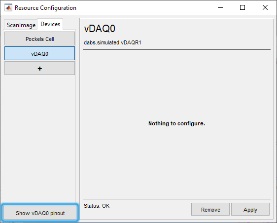
In ScanImage, open the Resource configuration window from the startup dialog or from the Main Controls window under File>Configuration.
From the Resource Configuration window, select the “+” button. Select “DAQ” from the sidebar, and select “Simulated vDAQ”. Assign an arbitrary a name and continue
The simulated vDAQ does require any further configuration. Select the button “Show vDAQ0 Pinout” to show the breakout panel of the vDAQ.
Below is an example of a pinout window that would be seen after configuring a simulated pockels cell with simulated vDAQ ports. This pinout window can also be shown by clicking on the vDAQ0 widget in the sidebar.
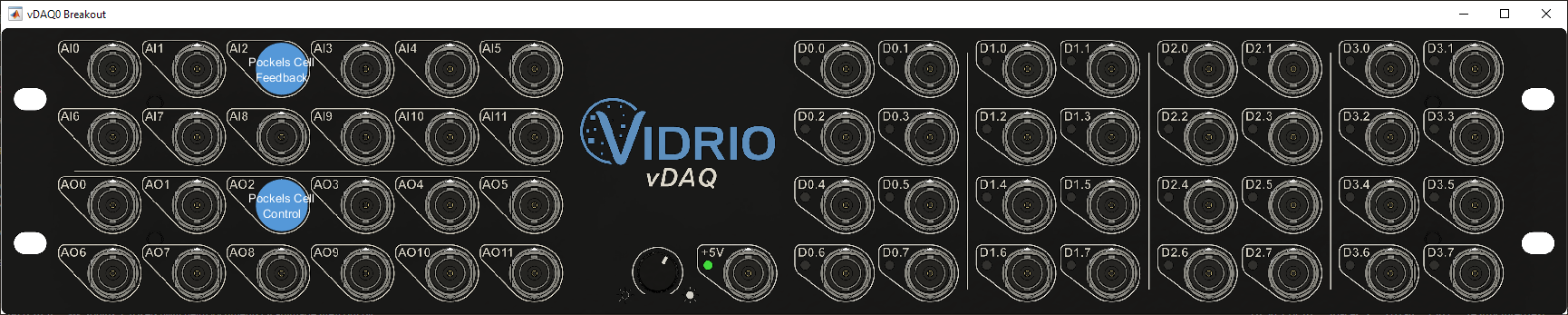
A simulated vDAQ allows to configure an entire microscope system without any physical hardware connected to the computer.
For example, a user wanting to simulate an RMR scanner could configure a Vidrio RMR device and then follow the premium feature tutorials for Multiple Region of Interest (MROI) Imaging, Arbitrary Line Scanning, and Photostimulation
Focus Acquisitions will work with a simulated image being acquired.
Note
with simulated devices configured with a simulated vDAQ, feedback signals are not simulated, so Waveform Optimization and other features making use of analog inputs cannot effectively be simulated.
Sample Wiring Diagrams
Wiring Diagrams are provided as a convenience. they can be printed out and serve as a checklist when making connections if their configuration suits the intended application. The vDAQ could be connected to devices like so:
Description |
Link |
RGG, Pockels, Shutter, Fast Focus |
|
Thorlabs Bergamo scope |
|
Thorlabs Mesoscope |