Digital Shutter
Digital shutters are devices that accept a digital TTL signal to block or unblock a laser.
Since shutters are a safety relevant part of the microscope setup, special attention is required to ensure the setup is configured correctly.
Attention
Special care is taken in ScanImage to ensure the main shutter is only open during an active imaging session. However, during operation the shutter can open unexpectedly or remain open if a software fault occurs.
To avoid injuries, it is recommended to manually override the laser shutter to the closed position before using the microscope eyepiece or working on the optical path of the microscope.
Warning
Some shutter controllers are configured to open the shutter if the digital input is unconnected. This can be a safety issue since the vDAQ and NI DAQ boards and NI FPGAs default to the output configuration ‘Tristate’ on startup.
Default DO States
Digital output lines on the vDAQ and NI DAQ boards and FPGAs support three logic levels.
Logic Level |
Output |
|---|---|
Low |
digital ground |
High |
+5V |
Tristate |
high impedance |
The tristate output effectively removes the digital output line from the circuit. This means that the circuit connected to the digital output lines behaves as if the line was unconnected. Tristate is the default output of all DIO lines on the vDAQ, all digital output lines on a NI DAQ board, and a NI FPGA when the device is powered up. The state only changes if another value is actively set via software. This means that from the time the data acquisition system is powered on to the time ScanImage is first started, the shutter controller is effectively unconnected / uncontrolled.
Consequently, it is essential that the shutter is configured to remain closed until it is actively controlled to open. Some shutter controllers implement a pull up resistor on the digital line controlling the shutter state. This means the shutter circuit ‘sees’ a +5V signal on the input line and therefore opens the shutter if the DAQ’s output is tristate:
Logic Level |
Output |
Shutter |
|---|---|---|
Low |
digital ground |
closed |
High |
+5V |
open |
tristate |
high impedance |
open |
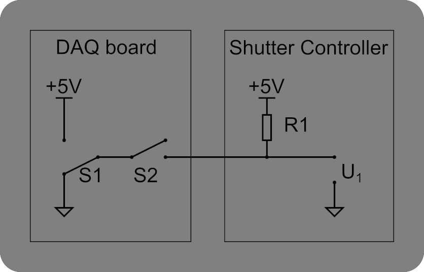
Equivalent circuit of a DAQ’s Tristate output
Since the switch ‘S2’ is open, the digital output is effectively ‘removed’ from the circuit (i.e. output is high impedance). If the input line of the shutter controller is connected to +5V via a pull-up resistor, the voltage accross U1 is 5V, which means the shutter opens.
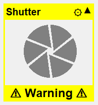
ScanImage will check the state of the pin during initialization to determine if the digital shutter control line is incorrectly pulled up or low. If it is, it will display the following warning on the widget.
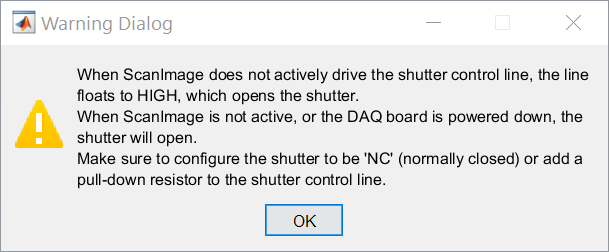
It will also display a pop up window with similar guidance as is given on this page:
Tip
A manual way to check if your shutter controller behaves correctly is to disconnect the digital output controlling the shutter from the controller. If the shutter opens when disconnecting the output line, the shutter may open unexpectedly while not actively controlled by ScanImage.
If your shutter controller is configured to be normally open, contact the shutter manufacturer to learn how to reconfigure the shutter to stay closed if unconnected.
Optical Config
Place the shutter after the pockels cell or other beam modulator in the beam path to avoid the effects of varying temperature on the performance of the beam modulator.
Hardware Config
Connect a BNC cable between a DAQ digital output and the TTL signal input of the Shutter controller.
Warning
If the shutter controller has a NC (Normally closed) and NO (Normally open) selection, select the setting NC (Normally closed). This ensures that the shutter will close when ScanImage does not actively drive the shutter (e.g. when the computer / the DAQ is powered off).
Uniblitz VMM-D1
If your shutter is controlled by a Uniblitz VMM-D1 Shutter controller, then it is essential to configure the controller to ensure safe operation.
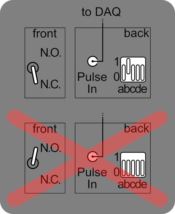
Top: Correct configuration for use with ScanImage: The toggle switch is in position ‘Normally Closed’. Switch ‘B’ is set to configure the Pulse In terminal to active high.
Bottom: Incorrect configuration; The toggle switch is in position ‘Normally Open’, Switch ‘B’ is set to configure the Pulse In terminal to active low. This double inversion works correctly while ScanImage is operating, however the shutter will open if the Pulse In terminal is unconnected or after a power cycle of the data acquisition system.
Please review the VMM-D1 manual for further information.
Software Config
In ScanImage, open the Resource configuration window from the startup dialog or from the Main Controls window under File>Configuration.
From the Resource Configuration window, click the “+” button. Select Shutter from the sidebar, and select “Digital Shutter”. Give it a name and continue.
A window like shown below will be displayed. Below the image is a description of each of the configuration parameters
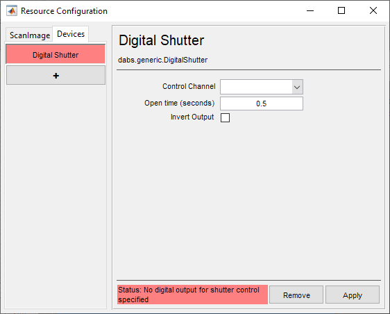
Control Channel |
The DAQ/AO-Port# which was physically connected during hardware setup to the driver command input |
Open time [seconds] |
The settling duration between when the command is first given to open the shutter and when it has actually fully opened. |
Invert Output |
If checked, inverts the digital output signal such that TTL Low corresponds to shutter open and TTL High corresponds to shutter closed. |
Path |
Whether the shutter is place between the sample and the laser (excitation), or the sample and the PMT (detection). Note The default state of the driver is such that 5V (TTL High) corresponds to opening the shutter. |
The sidebar will add a shutter widget which indicates the state of the shutter based on the configuration. You can toggle the state of the shutter by clicking on the image.