Sample Tracking Power Boxes
Added in ScanImage 2022.1.0, Sample tracking power boxes allow the user to define power boxes that account for stage position to keep the power box located over a particular area of the sample. Power boxes give control over how much laser power is applied to a particular area.
Suggested benefits are as follows:
Blank laser over parts of the sample that should never receive laser power (E.g. eyes of zebrafish)
Account for non-uniform skull thickness in 3P microscopy with or without skull thinning
In ScanImage 2023.0.0, the capability to use motion detection was added to correct for any slow sample motion not already captured by the a change in motorized stage position. All that is required to enable this functionality is to enable motion detection.
In ScanImage 2023.1.0, this is made more apparent by moving the power box display in the ROI Group Editor with the detected motions.
Prerequisites
Hardware
A fast beam modulator of suitable bandwidth for the pixel rate.
This feature is supported by both the vDAQ and National Instruments DAQs for linear scanning or resonant scanning.
An aligned camera is recommended if the motivation is to reduce laser exposure to sensitive areas.
Alignments
A stage-scanner alignment is required. The alignment improves the relation (scaling, rotation, possibly shear) from scanner optical degrees to microns in sample relative space which is used to determine precisely where to shift the power box when moving the stage.
Tutorial
Aquiring a preview image
First, you need to know where power should be distributed relative to some image data plotted in the viewport. If a camera has been added and is aligned to reference space, then this is the suggested route for samples prone to damage from laser power (e.g. eyes of a zebrafish). Otherwise, grab a few frames with enough beams power to get a suitable image.
If desired for future reference, you can pin the image to the viewport.
To do so, press p on the keyboard to pin all displays to the viewport.
Adding a Power Box
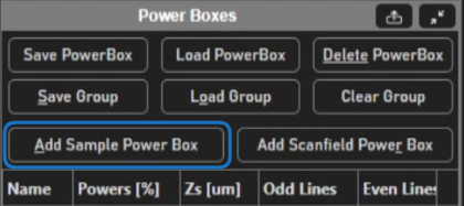
Power boxes can now be added and edited from the ROI Group Editor window. To add, click the Add Sample Power Box
button in the Power Boxes Gui of the Power Box Tab.
You will then be able to draw power boxes in the viewport.
There are a few controls that you can use from the display of the power box.
Left-click over the surface and dragging will move the power box’s location in absolute coordinates
Left-click over the
+in the lower right corner and dragging will resize the power boxRight clicking the power box will toggle the power box to be defined relative to ROIs, which is how power boxes have worked in the past.
Overlaying the power box over the context image
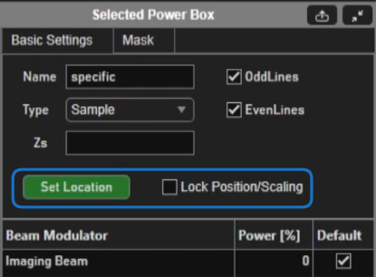
To overlay the power box over a previously acquired context image, Go to the Basic
tab of the Power Boxes GUI, and press the Set Location button. Then you can click
on a live image, pinned image, or live camera image in the field of view.
This should position and resize the powerbox to perfectly overlap the context image.
The power box location
can then be locked such that left click and dragging or resizing are disabled.
To do so, place a check in the Lock Position/Scaling check box.
Power Box Power
At this point, it is relevant to note the significance of the color of the power box.
Try this. Set the Power [%]
editable text to values 0, 50, 100, and NaN and observe color changes of the power box display.
While the Power [%]
is set to NaN, vary the power from the Acquistion Cotrols Gui window.
An orange hue in the power box display indicates that the power is set by the beam(s) slider(s) from the acquisitoin controls gui.
(effectively bypassing the powerbox).
A red hue indicates that power is set using the percent specified in the Power [%] editable text. The alpha of the surface indicates the
level of laser power.
About Power Box Mask
Click the mask tab in the Selected Power Box GUI.
To enable a mask, place a check in the Enable Mask check box, and
this will enable the mask editing user interface elements.
The power box mask allows you to vary the power within the scanned part of the power box.
The mask is a M x N matrix of numbers between 0 and 1 inclusive, essentially like a grayscale image.
Each pixel of the mask is mapped spatially by its indices, and its value is the fraction of the power specified
from the Power [%] editable text. If a pixel value of the mask is NaN,
the power as specified from the beam controls window is used. If the Power [%] is NaN, then a pixels value is
the fraction of beam power as specified from the beam slider in the acquisition control gui.
Setting Power Box mask from a context image
To quickly and easily paint a mask that makes sense for what you are imaging, you can use image data from the veiwport.
From the Context Image Import panel, Take from Background.
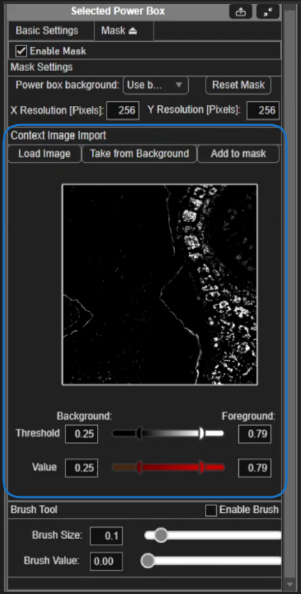
To assign mask pixel values from the image, it is useful to separate a background from the foreground.
The background shall be defined as black pixels in the mask preview and the foreground shall be defined as the white pixels.
To distinguish the background of the image from the foreground of the image, click and drag the left-hand Threshold
slider. As this slider changes position, the brightness of pixels in the mask preview display will change. All
black pixels will be assigned the background value that can be specified as either NaN or Zero from the Power box background dropdown.
Pixels in the image that span from black to white (exclusive) will have their powers mapped to the range given by the left and right-hand Value sliders.
All the white pixels will have the power specified by the right-hand Value slider.
In the case of imaging the zebrafish, it is desired to image with the power set from the beam controls window everywhere except over the eyes where the power should be fully minimized. For this, the eyes will be the background of the image with background set to zero power.
To do this:
Select
Zerofrom thePower box backgrounddropdown.
2. drag the right-hand threshold slider to meet the left-hand slider so they are the same value, and then drag the left-hand slider to the right
to move both the left and right hand slider maintaining equality between the two. Watch the preview window while sliding to find a threshold that contains just the eyes.
Drag the left-hand
Valueslider all the way to the right to set both left and right values to 1.Click the
Add to maskbutton to add the mask to the power box
Click the Reset Mask button to set the whole mask to the background value if desired.
The resolution of the mask can be set in pixels. The quality of the mask is foremost determined by the resolution of the mask, but also constrained by how many beam samples can be issued within the duration of a line and also the bandwidth of the EOM/EOM controller.
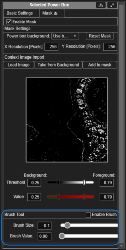
Painting the mask
It may not be possible to perfectly capture areas that should or should not have laser exposure using the context image. In the case of the zebrafish, there are several dark parts of the mask preview which we don’t mind exposing to laser power. To compensate, we can paint pixel values onto the mask directly.
Place a check in the Enable Brush box. You can set the Brush Value and Brush Size from the sliders. In the case of the zebrafish, we want to
set the Brush Value to 1. Now, left click and right click behave differently when used while hovering over the power box display.
Left click will paint the value set in the Brush Value editable text box while right click will erase the mask to the currently set background value.
We can paint with left click and dragging over parts of the zebrafish that should still receive laser power.
We can just as well set the Power box background to Use beam controls and then right click and drag over parts of the image and it will have the same
effect - using the power as set from the beams sliders in the Acquisiton Controls GUI.
Note
Orange pixels in the power box display (mask or no mask) indicate that the power set within the orange regions will use power set from the beam controls.
Executing the power box
To execute the power box, place a check in the Enable Power Box checkbox before or during acquisiton mode. The beams will now be modulated according to the mask, and stage moves will follow the sample if properly aligned. When a move is initiated from ScanImage, the beams will be blanked until the stage settles to avoid unnecessary exposure.
Caveats
As line rate increases with constant sample rate for beams control, the number of beams samples per line decreases. Thus the time resolution of beam control can be cumbersome for fast scanning modalities like resonant scanning. To illustrate, max DAQ analog output rates are as laid out in the table below.
vDAQ
2 MHz (simultaneous for all channels)
PXIe-6341 and PCIe-6321
900 kHz (single channel)
PXIe-6363
2.86 MHz (single channel)
PCIe-6376
3.3 MHz (simultaneous for all 2 channels)
If resonant scanning with an 8 kHz scanner, providing a line rate of 16 kHz while bidirectional scanning, the samples per line is the DAQ AO sample rate divided by the line rate multiplied by the temporal fill fraction. For the vDAQ, this would be ~89 samples per line with a spatial fill fraction of 90%.
In actuality, the sample rate used for the beams is not often set to the max sample rate, so the actual number of beams samples per line is less. To see the sampling rate of For details on how the sample rate is chosen, see the Scan2D and corresponding control class code for you imaging system.
This feature relies heavily on the sample stage’s ability to accurately report its position. Any offset developed between the stage’s true position and its reported position will manifest itself in imaging.