Fast Beam Modulator
Both pockels and fast beam modulators refer to this page as the two use the same driver - dabs.generic.BeamModulatorFastAnalog.
ScanImage® controls the laser power for two reasons:
Controlling the amount of power delivered to the sample
Blanking the laser power during mirror turnaround to avoid photodamage in the sample
While any beam power modulation device that accepts an analog input signal can be used for power control with ScanImage, the most common modulation device is a Pockels Cell. This article describes the setup and configuration of Pockels Cells for the use with ScanImage. It also describes troubleshooting steps if the modulation does not work as expected.
Supported Devices
Controller Hardware |
Compatible Devices |
ScanImage® Driver |
all |
||
(combined controller and device) |
Optical Setup
A Pockels Cell splits the input beam into a ‘transmitted beam’ and into a ‘rejected beam’. The transmitted beam is used for illuminating the sample, while the energy of the rejected beam is dissipated in a beam dump. By changing the control voltage of the Pockels Cell, the power ratio between the transmitted and rejected beam can be adjusted. The Pockels Cell power modulation is non-linear in respect to the control voltage. To compensate for this non-linearity, ScanImage® creates a look-up table that translates a desired power fraction into a control voltage. To measure this look up table, a photodiode is placed either in the transmitted beam or the rejected beam. To avoid over-exposure of the photodiode, a small fraction of the beam is picked off, and a ND-filter is used to further reduce the beam intensity at the photodiode.
Photodiode Option 1: Beam Pick-Off |
Photodiode Setup Option 2: Rejected Light |
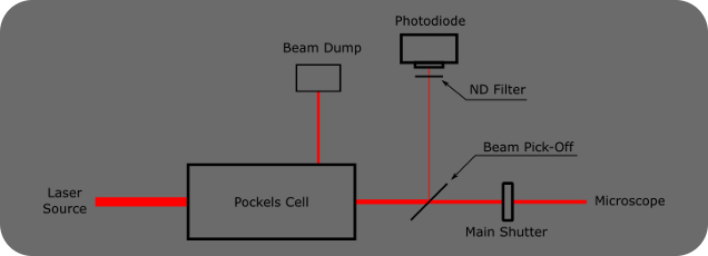
Option 1 A beam pick-off after the Pockels Cell directs light to the photodiode. ScanImage® must be configured for ‘Transmitted Light’ |
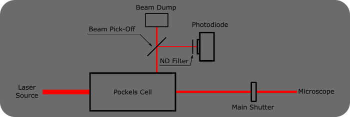
Option 2 The photodiode is positioned in the rejected beam of the Pockels Cell. ScanImage® must be configured for ‘Rejected Light’ |
Note
The Pockels Cell power modulation is temperature dependent. If the microscope’s main shutter is placed before the Pockels Cell, the cell heats up while the shutter is open and cools down when the microscope is inactive and the shutter is closed. To ensure the Pockels Cell is remains in thermal equilibrium, the shutter should be located after the Pockels Cell.
Hardware Setup
Connect the Pockels Cell to the high voltage driver as described in the user manual. Connect the command input on the driver board to an AO (analog output) of the ScanImage® system. Connect the Photodiode to an AI (analog input) on the same DAQ board as the command signal.
Note
In a resonant scanning system with National Instruments data acquisition hardware, the Beam Modulation device requires its own DAQ card apart from other devices which also utilize NI DAQmx timed tasks, e.g. scanners or fast focus devices.
Note
To accurately measure a look up table for the Pockels Cell, it is important that the photodiode gain is appropriately set, so that it has sufficient signal at the low end, but also does not saturate at the high-end. Incorrect photodiode gain is a common source of Pockels calibration errors.
Some drivers may require additional configuration steps:
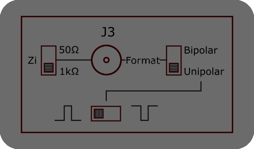
Conoptics 302RM driver settings
ScanImage® requires the Conoptics 302RM driver to be set to 1kΩ impedance, non-inverting unipolar input.
Conoptics 302(RM)
For a Conoptics 302(RM) driver, the switches should be set as indicated in the graphic to the right.
Note A high voltage offset can degrade the Pockels Cell over time. With the driver input at 0V and the voltage offset at 0V, rotate the Pockels Cell around its optical axis until the transmitted power is at its minimum. The power modulation of the Pockels Cell depends on the polarization of the input beam. After the rotational alignment of the Pockels Cell, the polarization of the input beam should not be changed. |
ScanImage® Configuration
In ScanImage, open the Resource configuration window from the startup dialog or from the Main Controls window under File>Configuration.
From the Resource Configuration window, click the “+” button. Select Beam Modulators from the sidebar, and select either “Fast Beam Modulator” or “Pockels Cell”. They point to the same driver. Give it a name and continue
A window like shown below will be displayed. Below the image is a description of each of the configuration parameters
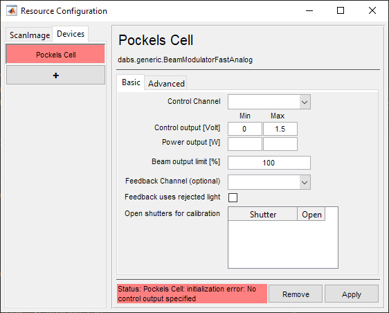
Control Channel |
The DAQ/AO-Port# which was physically connected during hardware setup to the driver command input |
Minimum control output [Volt] |
The least, or most negative, output voltage to be sent to the controller |
Maximum control output [Volt] |
The highest output voltage to be sent to the controller |
Minimum power output [W] |
The power in watts of the laser when the the Control Channel is outputting the minimum control output voltage |
Maximum power output [W] |
The power in watts of the laser when the the Control Channel is outputting the maximum control output voltage |
Beam output limit [%] |
An arbitrary limit to the power of the laser based on interpolation from above control output and power entries |
Feedback Channel (optional) |
The DAQ/AI-Port# which was physically connected during hardware setup to the driver feedback output Note This is to provide linear control of laser power as the beam power does not have a linear relationship with control signal voltage by default. |
Feedback uses rejected light |
If statement is true based on the Optical Setup, then check this box |
Open shutters for calibration |
When shutters have been configured, they will show in the table. If the beam modulator is positioned post shutter, then ScanImage® can be configured to open the shutter when doing a calibration. Warning Again, the Pockels Cell power modulation is temperature dependent. If the microscope’s main shutter is placed before the Pockels Cell, the cell heats up while the shutter is open and cools down when the microscope is inactive and the shutter is closed. To ensure the Pockels Cell remains in thermal equilibrium, the shutter should be located after the Pockels Cell. |
Note
minimum control output does not necessarily have to correspond to the minimum power output;
maximum control output does not necessarily have to correspond to the maximum power output.
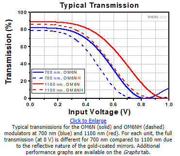
In the case of Thorlabs OM6N(H), maximum power output occurs at the minimum control output of 0V. The curve shown from Thorlabs’ graph should be replicated in ScanImage’s own graph shown after calibrating (see below).
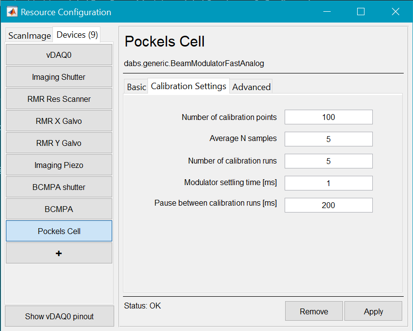
Calibration Settings
Calibration is crucial to know how much power is actually being applied at the sample. The process is such that the command voltage is swept from minimum to maximum control voltage while measuring voltage from a photodiode. Calibration of beam power requires that as voltage goes from minimum to maximum control voltage, there is a voltage interval within which yields the minimum photodiode voltage to the maximum in a monotonically rising or falling curve. Electrical noise or stray light can affect this measurement and cause failure of the calibration procedure, so the following settings are made available to cope.
Number of Calibration Points |
The number of points to collect in a single run, a run being data collected during a sweep from the minimum control output voltage to the maximum. |
Average N samples |
For each calibration point, this is the number of samples that are averaged to calculate each point. |
Number of calibration runs |
This is the number of sweeps used to form an averaged calibration curve |
Modulator settling time [ms] |
This is the duration of delay between sending a new command voltage to the controller to when data is collected from the photodiode. |
Pause between calibration runs [ms] |
This is the amount of time to pause between calibration runs allowing the modulator to go from maximum to minimum beam power. |
Advanced
These settings are available for National Instruments hardware users who need to use both PXIe and PCIe DAQ cards to accommodate the needs of the experiment. If the beam modulator is configured to be controlled from a PCIe DAQ while acquisition is controlled from a PXIe DAQ, then a reference clock and beam (for scanning) or frame (for linear scanning) are required to use the beam modulator for raster scanning.
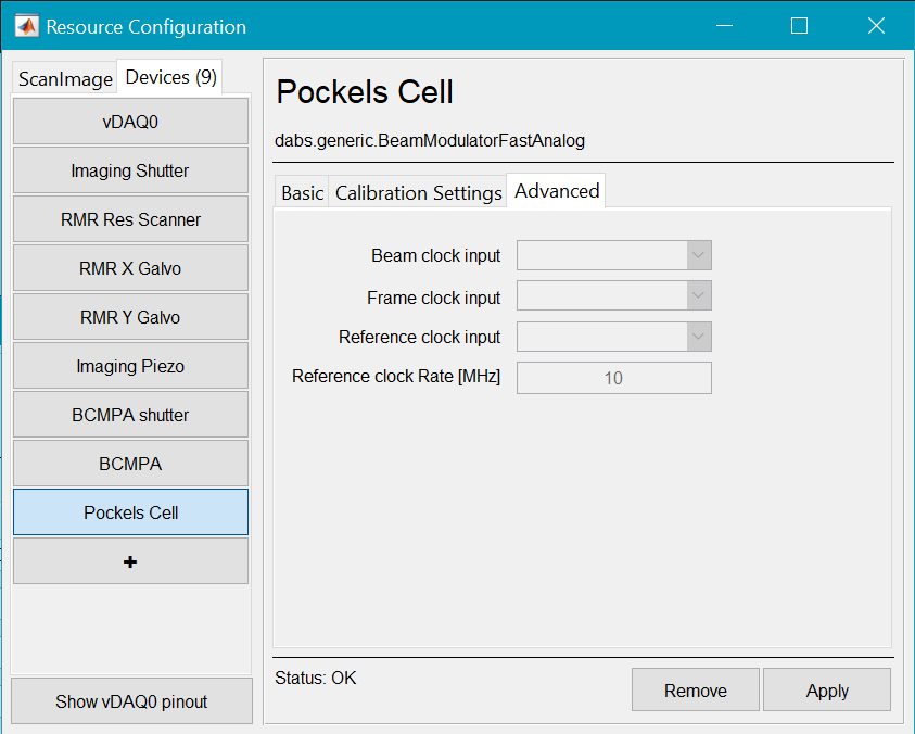
Beam Clock Input |
The number of points to collect in a single run, a run being data collected during a sweep from the minimum control output voltage to the maximum. |
Frame Clock Input |
For each calibration point, this is the number of samples that are averaged to calculate each point. |
Reference Clock Input |
The port which should receive the reference clock provided by the digitalIO DAQ for National instruments linear or resonant scanning imaging systems, the reference clocks are output on terminal PFI14 of the Digital IOD AQ or Aux DAQ. |
Reference Clock Rate [MHz] |
The rate of the Reference clock of the acquisition system. Should be 10 MHz for either linear or resonant scanning. |
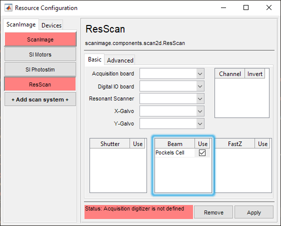
Click Apply to apply the configuration to this device. It can now be used as a beam modulator for a ScanImage® imaging or photostim system.
Calibration
The Pockels Cell power modulation is non-linear in respect to the control voltage. To compensate for this non-linearity, ScanImage® creates a look-up table that translates a desired power into a control voltage. After the Pockels Cell is configured, follow the steps below to create a look up table. See the Beams Concepts page
Note
The look-up table depends on the operating temperature of the Pockels Cell and the wavelength of the laser. It is recommended to recalibrate the look-up table before the start of every experiment to ensure the power modulation is reliable.
Beam Alignment
When ScanImage® is idle, the scanners are parked, the shutters are closed and the Pockels Cell does not transmit light. For alignment, select ‘Point’ in the ScanImage® Main Controls window. This will open the shutter and center the mirrors. To allow light through the Pockels Cell, change the slider in the Beam Modulator widget in the widget bar to the desired power. To abort the alignment, select the ‘Abort’in the Main Controls. This will park the scanners, close the shutters and disable transmission through the Pockels Cell.
Imaging
During imaging, change the slider in the Power Control GUI to change the laser power.
Note
ScanImage® blanks the beam during scanner turnaround to avoid overexposing the sample. Since the Pockels Cell does not respond to a changed control voltage instantaneously, the image can show blanking artifacts on the left and right edges. ScanImage® can compensate for this effect by shifting the command voltage in time. This time shift can be set in the field ‘Beam Lead Time’ in the Power Controls Window. Typically, a value of 2us is sufficient.