Cameras
ScanImage® features support for cameras to view a widefield image of the sample. This feature can be used to register the widefield camera to the scanner, and find imaging areas from a previous session.
Attention
Not intended for Acquisition
ScanImage® introduces support for using cameras for wide field imaging. Currently camera support is limited to viewing at 30Hz. It is not intended to be used for fast data acquisition or capturing image data to disk.
Configuring a Camera
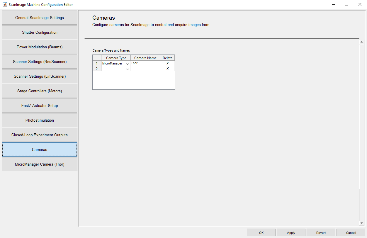
Cameras are configurable from the Machine Data File Cameras Tab. The table contains a drop down menu to select cameras based on their type from a list of supported cameras or camera drivers, as well as a field to name the camera.
Accessing Configured Cameras
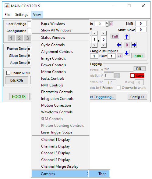
Cameras, once configured, are available from the Main Controls window of ScanImage® under View->Cameras and are listed by name as entered in the MDF. The previously configured µManager ThorLabs camera is listed as Thor. Clicking on this will launch the camera control interface window for the selected camera.
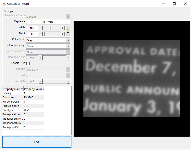
Camera Controls Interface
The camera controls interface window, right, is the primary window for controlling configured cameras. On this window are a number of UI controls for various aspects of the camera which are detailed below.
|
Coordinate space for the live view: Camera: Camera coordinate space ROI: Scanner coordinate space
|
|
Sets the camera exposure time in ms |
|
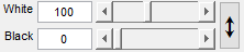
Sets the black and white levels for the image display Look Up Table. Pixel values greater than White level are set to the maximum pixel value and values below Black level are set the minimum pixel value. Pixel values between Black level and White level are linearly interpolated for display. The vertical double arrow automatically adjusts the Look Up Table. |
|
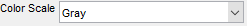
Sets the color scale for the live view. Options: Gray, Red, Blue, and Green. |
|
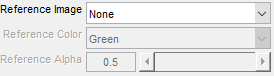
For finding regions from a previous session, reference images can be loaded from files (Tiff or PNG). Reference Color: Sets the color scale of the reference image Reference Alpha: will adjusts the transparency of the reference image.
|
|
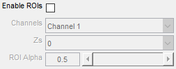
Enables the scanner overlay either from the default imaging ROI or from multiple ROIs if mROI mode is enabled for camera to scanner alignement. Below the enable are options to select PMT channel source, Z planes where ROIs are defined as well as ROI alpha to control transparency of the ROIs. |
|
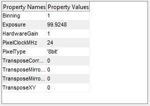
This table exposes dynamic properties specific to the camera.
|
|
Stops and starts the live acquisition of frames from the camera. |


Camera to Scanner Alignment
Scanner alignment is performed as per the Scanner Alignment tutorial.