PhotoMultiplier Tube
A Photomultiplier Tube (PMT) is a photon detector, that outputs a current signal when a photon is detected. The current is converted into a voltage signal by a transimpedance amplifier. The voltage signal is ultimately converted to a digital signal by a digitizer.
Below is some information about PMTs that is commonly true regardless of the model.
Transimpedance Amplifier (TIA)
TIAs vary in the bandwidth of signals that they are able to amplify. The bandwidth of the amplifier required for your microscope depends on the sample rate and shortest pixel durations provided by your scanning configuration.
For resonant scanning a bandwidth of at least 30 Mhz is recommended.
Commonly used transimpedance amplifiers are
Some PMT models have built-in TIAs (e.g. Thorlabs PMT2000).
Hardware Setup
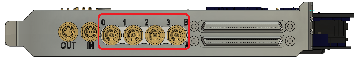
Connect the output of the transimpedance amplifier to the ScanImage digitzer:
vDAQ: AI0-AI3 on the vDAQ frontpanel
FlexRIO adapter module: Analog inputs available on front panel
DAQ board: Analog inputs on breakout board
ScanImage® Configuration
ScanImage® has several drivers for PMT control:
Calibration
ScanImage® acquires voltage signals on each of the enabled input channels. Ideally, the voltage value of 0 would correspond to zero signal, i.e. zero detected photons. In reality however, the input digitizer channel and connected detector electronics (e.g. PMT amplifiers) combine to exhibit:
A non-zero offset value
A distribution of noise values centered on the non-zero offset value
ScanImage® can measure and, optionally, subtract/correct these offset values. Measured offset values are stored in the header (metadata) of saved ScanImage® TIF images, within the property ‘channelOffsets’. If offset correction is applied by ScanImage® (or applied by user in post-processing) a histogram of image data will show a symmetric noise distribution centered on zero (with half negative values) and a positive signal distribution.
ScanImage® offset measurements are obtained with:
Scanner parked
Shutter closed (if shutter is configured)
Beam modulation fully attenuated (if Beam modulation is configured)
Attention
Measuring Accurate Offsets:
Because measured channel offset includes circuitry connected to input channel, for typical PMT-based input channels, the offset values will depend on:
whether PMT is on or off
PMT gain level applied
ScanImage® offset measurements can be obtained at various times:
Manually |
Press Read Offsets anytime to update offset value. |
Automatically at start of each acquisition (FOCUS, GRAB, or LOOP) |
Enable Auto Read checkbox to select this option. Note This option defaults to TRUE in ScanImage® 5 |