Laser Trigger Scope
Laser Trigger Scope Panel
Overview
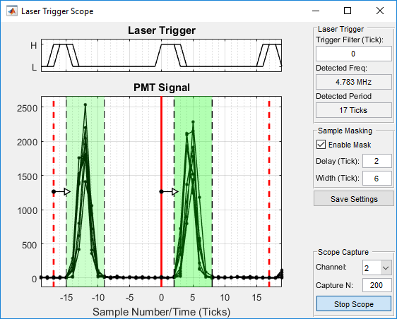
The Laser Trigger Scope panel is used for viewing and configuring a sampling window for low rep-rate laser support
Note
The Laser Trigger Scope panel can be accessed by selecting View->Laser Trigger Scope from the MAIN CONTROLS interface menu.
Main Panel
Laser Trigger Plot |
When the scope is active, this shows traces of the laser trigger. This can be used to determine if filtering is needed. The X axis is in “Ticks” with one tick equal to the sample rate of the digitizer. |
PMT Signal Plot |
When the scope is active, this shows traces of the PMT signal for the selected channel. The plot is overlaid with the sampling window in green that is applied based on the settings. The sampling window can be moved by clicking and dragging in the green area or resized by clicking and dragging the edges. |
Trigger Filter |
Sets the debouncing filter level for the laser trigger. Zero disables the filter while increasing the value increases the filtering |
Detected Frequency |
Shows the frequency of the detected laser trigger in MHz. This will update when the scope is enabled. |
Detected Period |
Shows the period of the detected laser trigger in ticks (digitizer sample periods). This will update when the scope is enabled. |
Enable Mask |
Enables masking of samples based on entered settings. When this is enabled changes to settings take effect immediately |
Delay |
Number of samples after laser pulse to ignore |
Width |
Number of samples to include after the ignored samples |
Save Settings |
Saves the entered settings to the Machine Data File. Saving settings avoids needing to repeat this setup again. |
Channel |
Select the acquisition channel to show in the PMT signal plot |
Capture N |
Set the number of samples to show in the plot. Data is divided at detected laser pulses and each detected pulse is plotted as a separate trace. Increasing this number will show more traces |
Start/Stop Scope |
Enables or disables the live scope display. |