Fill Fraction
Motivation
At the very edges of the resonant mirror’s scan field the angular velocity of the resonant mirror is low, so that the laser power is attenuated in this region to prevent the sample from burning. Additionally, the acquisition is inactive, so that no pixels are formed in this region.
Definition
The fill fraction is defined as ratio between the length of an active acquisition of a line and the total length of the line. The fill fraction can be expressed temporally (ft) and spatially (fs), and can be calculated with the following formulas:
Temporal Fill Fraction (ft) = line acquisition time / line scan period
Spatial Fill Fraction (fs) = angle of active acquisition / scanner angular amplitude
The relationship between the spatial fill fraction and the temporal fill fraction can be expressed as
fs = cos( (1-ft) * pi/2 )
To adjust the fill fraction, use the Fill Fraction controls in the Configuration Panel.
Note
When the fill fraction is changed, the Y-galvo scan range is changed accordingly to maintain a square pixel ratio.
Beam-Modified Line Clock
ScanImage® generates a beam modified line clock to attenuate the laser power relative to the active acquisition. This clock is used in the Beams module to control the Pockels Cells for fast modulation of the laser beam.
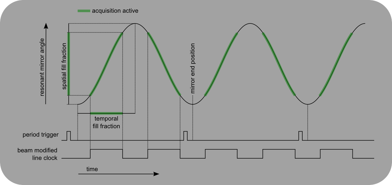
Spatial and Temporal Fill Fraction
The fill fraction determines the width of the active acquisition over a line. The beam modified line clock is generated by ScanImage® to attenuate the laser power during the inactive portion of the scan.

Scan Field and Beam Blanking
The scan path of the laser beam determines the scan field. The actual image field is only a portion of the entire scan field. The width of the image field relative to the scan field is determined by the Fill Fraction.