Power Controls
POWER CONTROLS Panel
Overview
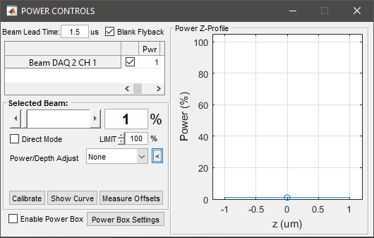
The POWER CONTROLS panel pertains to the (optional) control of a voltage-controlled light modulator (typically a Pockels cell), allowing the power level used during image acquisition to be controlled.
Note
The POWER CONTROLS panel only appears on ScanImage® startup if at least one beam DAQ is configured with at least one beam channel in the Machine Data File.
Main Panel
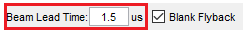
|
Specifies the time to advance beam control to compensate for lag in the response of the light modulation device. |
|
Specifies whether or not to blank the light modulation outside the line acquisition period, during frame flyback, and during fastZ flyback frames. |
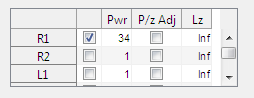
|
Lists all beams configured in the system and some settings for each. The checkbox in the first column selects which beam to display detailed settings for below. The rest of the columns mirror settings detailed in the next section. |
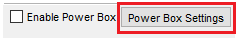
|
Enables power box |
|
Opens Power Box Settings GUI to modify power box parameters |

Selected Beam Panel
Note
The beam selected in the table above is the beam to which the settings in this panel apply.
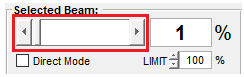
|
Slider control of the power level. Adjustments take effect immediately. Note During an active acquisition, each time the slider is moved the live output signals are updated. It is more efficient to move the slider to the exact desired position or use the number control than to repeatedly click the slider button. |
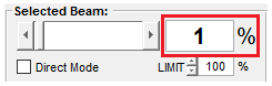
|
Direct numeric input of the power level. Adjustments take effect immediately. |
|
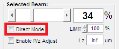
Normally, changes to Power have no immediate effect when not acquiring. For optical measurement & testing purposes, the Direct Mode option can be selected. This causes changes to the Power level to take immediate effect, i.e. Beam has specified power even though no scanning/imaging is being done. This mode can be individually set per beam. If any beam is currently in direct mode the checkbox is highlighted red. |
The Limit value simply determines the maximum value to allow for the Power level setting, for the specified Beam. This is useful for preventing the value from accidentally being set too high. |
|
|
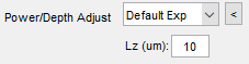
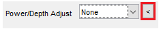
Drop down menu enables/disables Power vs. Depth adjustment feature and sets the method accordingly for currently selected Beam. Tip When collecting Image Stacks, step-wise or sweeping (i.e. Volume Imaging), in scattering tissue, the power level required at each slice in the stack generally increases with depth in order to maintain a fixed signal. ScanImage® can adjust the power automatically during stacks. |
|
Sets the Power vs. Depth adjustment function for the currently selected Beam to the default exponential function. Power is increased with depth according to: P = P0 * exp^((z-z0)/Lz) Note A value of Inf implies no power adjustment should occur for the selected Beam. Value of Lz must be positive - In general, the user will experiment to identify the Lz value suited for their preparation, which is typically fairly constant from acquisition to acquisition. Note the power level only adjusts in integer increments of the percentage value. The P/z Adjust and Lz controls are User Settings, i.e saved/loaded to User (.USR) files. Thus, once value is determined/entered by user for each Beam, these values are typically loaded when ScanImage® starts and apply to all stack configurations/acquisitions during that session. |
|
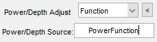
Sets the Power vs. Depth adjustment function for the currently selected Beam to the function indicated in the Power/Depth Source field. By Matlab convention this field indicates the name of the .m file containing the function definition to be used. The function name must match exactly the file name. The function should take the arguments startPower, zPowerReference, z in this order. The value and source of these arguments, whether or not they are actively used, as well as the manner in which they are combined is completely up to the user. PowerFunction example 1function powers = myPowerFunction( startPower,zPowerReference,z,lz)
2 powers = sqrt (z-zPowerReference).*startPower;
3end
|
|
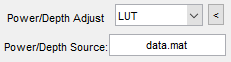
Sets the Power vs Depth adjustment for the currently selected Beam to follow an interpolation from a specified Look-Up Table given specified z depths. By SI convention the look up table should be an Nx2 matrix with column 1 containing z depths in microns and column 2 the corresponding beam power level for that depth. For z depths not specified in the LUT the default value is 10% power. The LUT can be any file format recognized by Matlab (.mat, .csv, etc). Warning On occasion, such as upon immediately starting ScanImage, the actual power output during GRAB operations will not update to reflect LUT values and will instead remain at a constant level equal to start power. It is recommended to always set start power to a very low setting when using a look up table to avoid damaging your samples. If this occurs it should be easily remedied by simply switching to default mode and then switching back. |
|
Collapses/Expands Power vs. Depth adjustment plot. This is provides a GUI based visual representation of power adjustment with respect to depth. |
|
Causes Beam Calibration for currently selected Beam to be remeasured. Note Many light modulators, including Pockels Cells, do not follow a linear relationship between the control voltage and output power. ScanImage® thus allows Beam Calibration, where the power transmitted as a function of control voltage is measured, using a light meter (typically a photodiode). Calibration data stored for each Beam determines voltage signal output to generate a specified percentage of the maximum power. Note Calibration curve is not displayed on successful calibrations - use the Show Curve button to see calibration results for a particular Beam If calibration curve appears noisy, non-monotonic, or otherwise suspicious, the calibration curve or raw calibration data is shown. Note For Beams without a calibration input (or if no acceptable calibration was maintained), a naive calibration is used where power is specified as a percentage of the beamVoltageRange entered in the Machine Data File <Machine Data File>. |
|
Displays Matlab figure showing result of most recent Beam Calibration obtained for currently selected Beam. |
|
Used to measure voltage offset on Beam Calibration input channel when no laser is present, i.e. offset of light meter and input A/D channel combined. User is prompted to block laser beam for the Beam Calibration offset measurement. All exiting and subsequent calibration curves are adjusted to reflect this input offset. |


Note
The Power level is stored/loaded as part of the ScanImage Configuration (.CFG) file.
KEY POINTS:
Power is adjusted to specified level immediately while actively imaging, or only when direct mode is on when idle.
Between acquisitions (i.e. between triggers), the Beam power level output is adjusted to minimum power measured during Beam Calibration – i.e. the Beam is ‘OFF’
The command signal generated by ScanImage® for selected Beam will alternate between the specified Power level and the minimum power (during scanner flyback or turnaround)