Thorlabs ECU 2 - PMT
Thorlabs ECU is controller box which is used as part of the BScope. The ECU2 is capable of controlling two scanheads - one for resonant scanning (for imaging) and one for linear scanning (for raster imaging, or Arbitrary Line Scanning or photostimulation).
Hardware Configuration
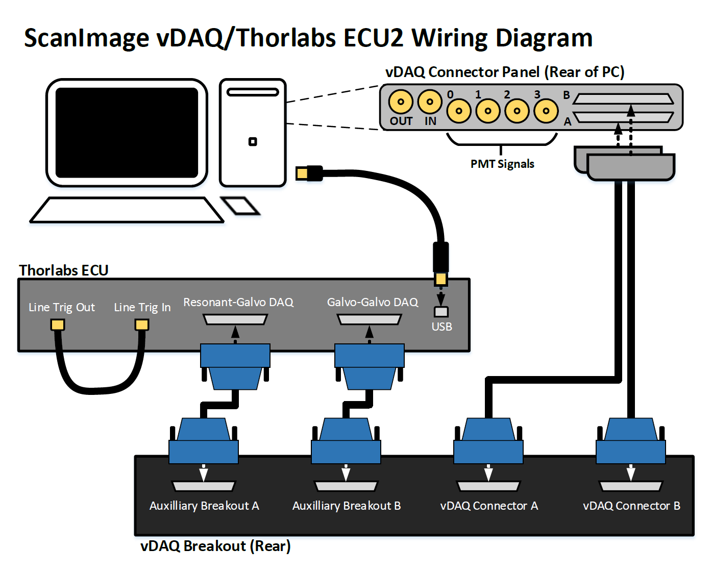
Use the below diagram to make all the applicable connections.
Software Config
In ScanImage, open the Resource configuration window from the startup dialog or from the Main Controls window under File>Configuration.
From the Resource Configuration window, click the “+” button. Select Thorlabs from the sidebar, and select Thorlabs ECU1 from the device list. Give it a name and continue.
A window like shown to the right should appear. Below is a description of each of the configuration parameters
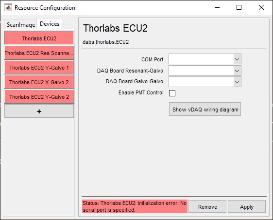
COM Port |
The COM port that is being used to connect the ECU to the PC Note Use windows device manager to determine the COM port by (while the ECU is switched off) unplugging and re-plugging the USB cable the port should appear under Ports (COM and LPT) |
DAQ Board Resonant-Galvo |
The DAQ board which has been configured to control the resonant-galvo scanhead |
DAQ Board Galvo-Galvo |
The DAQ board which has been configured to control the galvo-galvo scanhead |
Enable PMT Control |
Enable this checkbox to control a PMT which has been connected according to the diagram in the hardware configuration section of this page. |
Show vDAQ wiring diagram |
Press this button to see the vDAQ wiring diagram using a Thorlabs ECU |
One resonant mirror and 3 galvo mirrors are automatically added:
Imaging Path
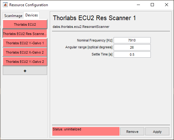
Nominal Frequency |
This is the frequency that the resonant scanner is expected to oscillate at. |
Angular range [optical degrees] |
This is the maximum range of the resonant scanner in optical degrees |
Settle Time [s] |
This is the time that ScanImage® will wait after beginning an acquisition to start acquiring fluorescence data. |
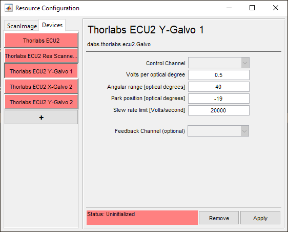
Control Channel |
The analog output channel used to control the deflection angle of the beam |
Volts per optical degree |
The scaling factor between control channel signal voltage and Y-Galvo beam deflection |
Angular range [optical degrees] |
The change in angle of the beam from one extent of the galvo’s travel to the other |
Park position [optical degrees] |
The Y-axis position component of the beam’s parked position. |
Slew rate limit [Volts/second] |
The rate at which the control channel’s signal voltage is allowed to change. Note For some galvanometer scanners with massive mirrors, it may be wise to limit the slew rate |
Feedback Channel (optional) |
The analog input channel used to receive the analog galvo position feedback signal for calibration and optimization. |
Stimulation Path
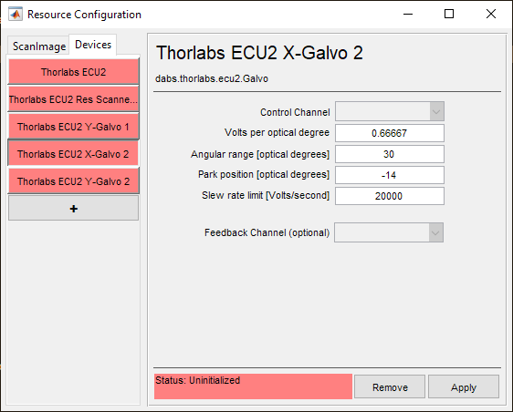
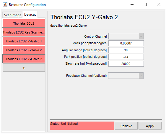
Control Channel |
The analog output channel used to control the deflection angle of the beam |
Volts per optical degree |
The scaling factor between control channel signal voltage and X-Galvo beam deflection |
Angular range [optical degrees] |
The change in angle of the beam from one extent of the galvo’s travel to the other |
Park position [optical degrees] |
The X-axis position component of the beam’s parked position. |
Slew rate limit [Volts/second] |
The rate at which the control channel’s signal voltage is allowed to change. Note For some galvanometer scanners with massive mirrors, it may be wise to limit the slew rate |
Feedback Channel (optional) |
The analog input channel used to receive the analog galvo position feedback signal for calibration and optimization. |