Scan Tab
The Scan Tab is where scanner configuration settings are defined including the active imaging scanner, the frame rate, and other options pertaining to scanning a particular scanfield.
- Related Documentation:
Tip
Hovering your mouse over some settings will reveal its location within the codebase (i.e. Pixels Per Line is scanimage.components.RoiManager.pixelsPerLine) or give background on the setting.
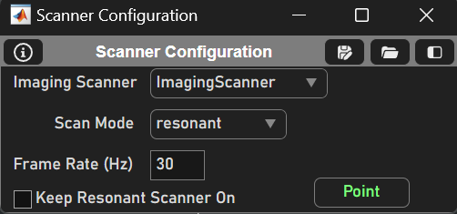
Scanner Configuration Panel
The Scanner Configuration Panel is where main scanner settings are set such as the active Imaging System.
Element |
Description |
Imaging Scanner |
Dropdown to select desired Imaging System. Note: Imaging Systems must be configured before ScanImage launches |
Scan Mode |
Dropdown to select scanning mode if applicable |
Frame Rate (Hz) |
Frame Rate of Imaging System given current settings. This is not editable directly, but calculated internally as 1 / (scanFramePeriod or Frame Time [ms]) |
Keep Resonant Scanner On (Resonant Scan Mode Only) |
Check to keep resonant scanner on (using this option can help avoid drift over time in the resonant frequency by allowing the scanner to “warm up” to a stable frequency) |
Stripe Display (Linear Scan Mode Only) |
Displays image stripes as they complete (see Striping Display for details). This option is checked by default |
Point/Park Button |
Points scanner at center of field-of-view (uses Shift Axes values), changing button to Park. Scanner remains pointed to field center until Park is pressed. While scanner is pointed, beam power is adjusted to specified level and shutter is opened (if such hardware is configured in Machine Data File) |
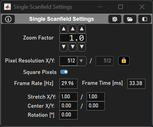
Single Scanfield Settings Panel
The Single Scanfield Settings Panel is where essential image settings are defined such as the frame rate, pixels per line, mirror zoom, etc.
Setting |
Description |
Zoom Factor |
Specifies the factor that the scan angular range is reduced, for both fast & slow dimensions, effectively ‘zooming’ the image. Adjusting zoom factor will set value to nearest allowed zoom increment. |
Pixel Resolution X/Y |
The number of pixels per line (X) and the number of lines per frame (Y). |
Lock (Force Square Pixelation) |
Forces the X and Y resolution to be equal. |
Square Pixels |
Forces Stretch Y = Stretch X * (X Resolution / Y Resolution). Otherwise, pixels may have a rectangular aspect ratio. |
Frame Rate [Hz] |
(Repeat) Number of frames per second. This is calculated by the scanfield variables. |
Frame Time [ms] |
Time to complete a single frame. |
Stretch X/Y |
Scales X/Y aspect ratio respectively. If the multiplier > 1, the scan FOV size is limited by the range of the X scanning mirror |
Center X/Y |
Moves the center of the X/Y scanner respectively. Negative values move the center left or up, positive values move it right or down. |
Rotation [°] |
This is the rotation counter clockwise about the Z-axis of the scanned area or line (degrees). This is for linear scanning only. |
XY Panel
The XY Panel is to configure settings for the galvos such as the galvo flyback time, the sampling rate of the digitizer, etc.
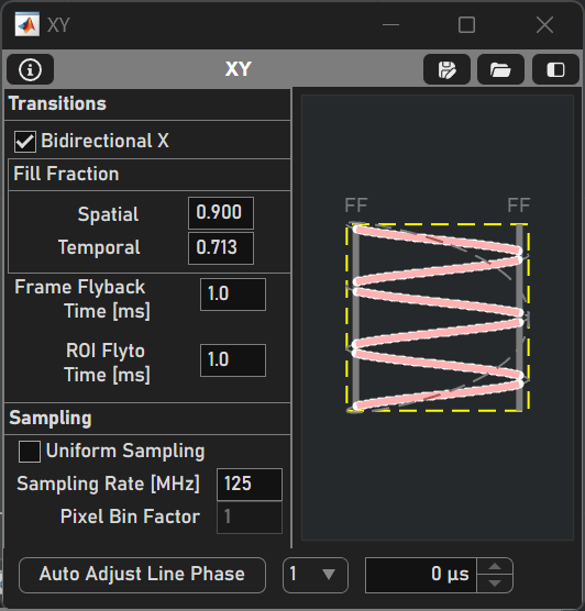
Transitions
Element |
Description |
Bidirectional X |
Enables two-way scanning (i.e. data is acquired when the X scan mirror is traveling in both directions). Bidirectional scanning increases frame rate, while unidirectional scanning can produce higher quality images by avoiding the interlace effect from the phase being slightly incorrect. |
Spatial Fill Fraction |
The ratio between the angular range of the scanning mirror and acquiring with the mirror. See Fill Fraction for details. |
Temporal Fill Fraction |
The ratio between the time duration of one mirror oscillation and time acquiring with the mirror. |
Frame Flyback Time [ms] |
The time it takes for the y-galvo to “flyback” to the start of the frame acquisition. |
ROI Flyto Time [ms] |
The time it takes for the galvos to move to the next ROI. |
Sampling
Element |
Description |
Uniform Sampling |
Uses a constant number of digitizer samples per pixel instead of applying the mask. When linear scanning, this is always the case. |
Sampling Rate [MHz] |
Sets the rate that ADC (analog to digital converter) samples are collected. If synchronization with an external clock is enabled, this will show the actual clock rate.
|
Pixel Bin factor |
The number of ADC samples that are ‘binned’ or averaged into one pixel. This is disabled when resonant scanning (see resonant scan mask). |
Line phase
Element |
Description |
Auto Adjust Line Phase |
Button that automatically attempts to correct for the line phase offset. |
Channel Dropdown |
Select the channel to adjust the line phase. |
Scan Phase |
Manually adjust the x mirror’s phase delay (in µs). |
Images
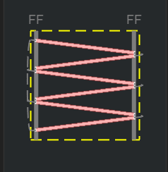
Raster (Linear scan) |
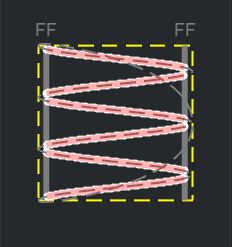
Raster (Resonant scan) |
The first image is a visualization of the laser raster scan pattern over the scanfield. FF represents the fill fraction (see resonant scanning concepts for more details). The image is slightly different for linear vs. resonant scanning.
Samples per pixel graph (Linear) |
Samples per pixel graph (Resonant) |
The second image is a graph relating the number of samples averaged together to create a pixel (pixel bin factor) vs. the # of pixels. While resonant scanning, a mask is calculated to correct for image distortion.
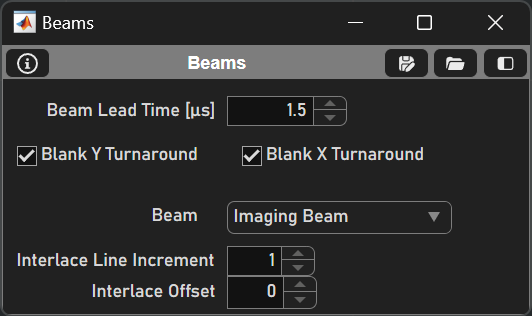
Beams Panel
Element |
Description |
Beam Lead Time [µs] |
The beam will be activated this many microseconds before the line starts (to account for the delay in the pockels cell). |
Blank Y Turnaround |
Blanks the beam during the Y galvo turnaround (Y flyback). |
Blank X Turnaround |
Blanks the beam outside of the fill fraction (X turnaround). |
Beam |
Select a beam to modify the beam’s settings. |
Interlace Line increment |
Setting so the beam is on every nth line where n is the line increment. |
Interlace Offset |
The specified line to start the interlacing lines. |