Zaber Stages
Zaber stages are implemented with a few extra features that are not available in the other ScanImage® motor drivers. This is stictly owing to the zaber MATLAB toolbox affording tight control; rich, open, and well-documented API, and sophistocated features of certain zaber motor controllers. These features include:
Live stage dragging from the display or the tile overviews window
Stage Scanning for motor controllers featuring the Streamed movement functionality
Hardware Config
Warning
Instructions here are no substitute for instructions that can be found in the product manual. Follow at your own risk.
Before configuring a Zaber stage in ScanImage, download the Zaber Console, connect to the stage and ensure to configure the stage as needed.
The ScanImage Zaber driver requires the Zaber Matlab Add-On. The ScanImage driver supports all Zaber stages that support the Zaber ASCII protocol (preferred) or the Zaber Binary protocol.
Note
Zaber devices can be connected in series (daisy chained). The ScanImage Zaber driver fully supports this mode of operation.
Check here for stream scanning hardware configuration.
Software Configuration
In ScanImage, open the Resource Configuration window from the startup dialog or from the Main Controls window under File>Configuration.
From the Resource Configuration window, click the “+” button. Select Motor Controller from the sidebar, and select Zaber Motor. Assign a name and continue.
Configure the ScanImage driver.
Basic tab
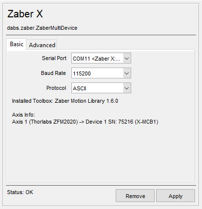
Serial Port |
Select the COM port assigned to the Zaber device |
Baud Rate |
Baud rate for the serial communications. Defaults are
|
Protocol |
|
Advanced tab
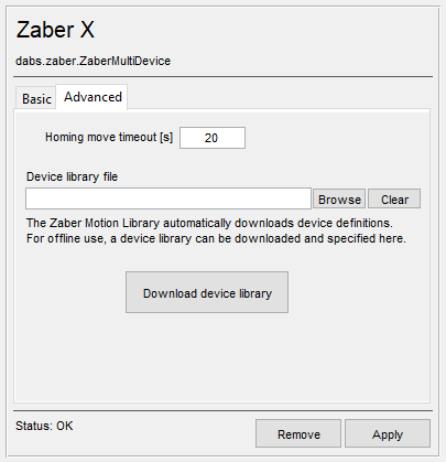
Homing move timeout [s] |
Time allowed for a reference move before an error is thrown. |
Device library file (optional) |
The Zaber driver stores stage parameters in a database file. If no file is provided, the default database is used. |
Stream tab
The stream tab will show up only if the Zaber device supports the Streamed movement functionality and has digital input IO. It will show up after the device has been configured with a COM port and the apply button has been clicked. The stream tab allows the user to configure a few parameters pertinent to stage scanning.
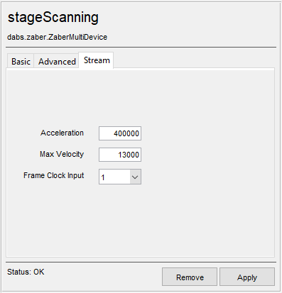
Acceleration |
Acceleration for the stage in um/s^2 |
Max Velocity |
Velocity for the stage in um/s |
Frame Clock Input |
The digital input terminal on the Zaber controller that will be used to trigger the stage movement. |
Once the device has been configured, it can be added to the ScanImage® imaging system via the left pane of the Resource Configuration window under the ScanImage tab after clicking the SI Motors button. This will reveal a page (see below) that will allow each of the axes to be configured as a XVSR40A axis.
Scaling factors are provided in addition to the configuration settings.
Note
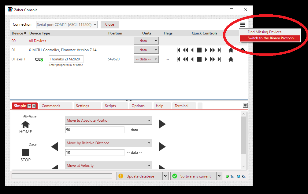
To switch a stage between ASCII mode and Binary mode, open the Zaber console, connect to the stage, click the three horizontal bars in the top right corner and select Switch Protocol.