Analog Motor Controller
This driver can be used with stages that allow position control via an analog control voltage in the range -10V to 10V.
Hardware Configuration
Connect a BNC cable between a free DAQ analog output and the motor controller signal inputs.
Software Config
Note
One Analog Motor Controller device is configured per actuated dimension of the stage. If you have 3 dimensions for your stage, you will configure 3 such Analog Motor Controller devices.
In ScanImage, open the Resource configuration window from the startup dialog or from the Main Controls window under File>Configuration.
From the Resource Configuration window, click the “+” button. Select Motor Controller from the sidebar, and select Legacy Motor. Give it a name describing the dimension that it actuates and click continue.
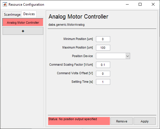
A window like shown below will be displayed. Below the image is a description of each of the configuration parameters

Minimum Position [um] |
The end of travel position associated with the most negative command voltage |
Maximum Position [um] |
The end of travel position associated with the most positive command voltage |
Position Device |
The analog output DAQ/port used to command the position |
Command Scaling Factor [V/um] |
The scaling factor to apply to AO signal to convert to position using linear interpolation |
Command Volts Offset [V] |
The offset to apply to the AO signal to convert to position using linear interpolation |
Settling Time [s] |
The duration after a move command is initiated to wait before a new move command can be initiated. |
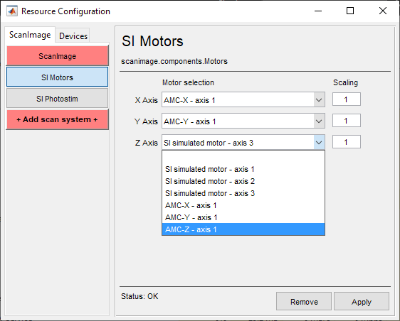
Once the device has been configured, it can be added to the ScanImage® imaging system via the left pane of the Resource Configuration window under the ScanImage tab after clicking the SI Motors button. This will reveal a page (see below) that will allow each of the axes to be configured as Analog Motor Controller devices.
Scaling factors are provided in addition to the configuration settings.

|

|