vDAQ Analog Data Recorder
ScanImage users that have a vDAQ can record from the low speed analog input ports using the Data Recorder. The Data Recorder stores data in HDF5 files and is configurable by the user.
Data Recorder Configuration Page
To configure the analog Data Recorder, add the Data Recorder to the devices in the Resource Configuration Window. Next, in the Data Recorder configuration window you can configure the properties of the Data Recorder based on your intended use case.
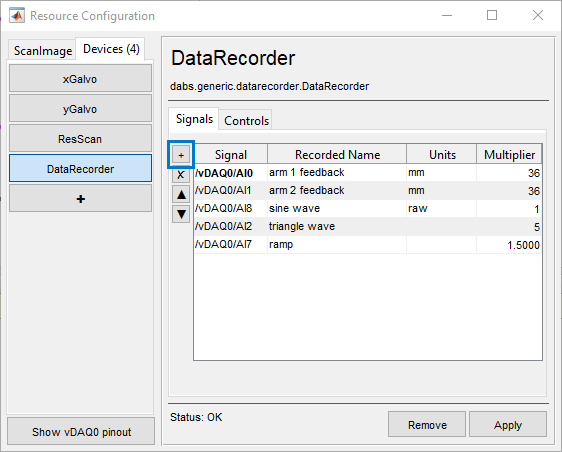
Add Signal: start by adding an analog input signal to the Data Recorder by clicking the + button. This will bring up a list of analog input signals to choose from, when you click a signal it will add to the table in the configuration window.
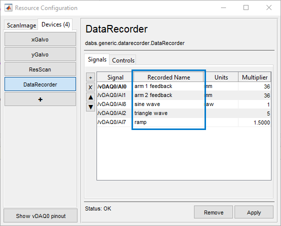
Signal Name: the signal name is the name of the HDF5 dataset that gets saved in the HDF5 file for that signal. You can name it however you want, however due to HDF5 naming conventions you cannot include forward slashes (/) in the name.
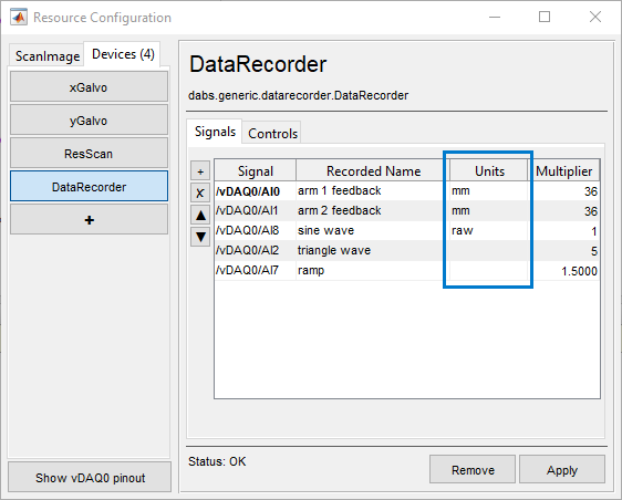
Signal Units (Optional): the units of the signal. This is stored as an HDF5 attribute in the dataset and can only be 63 characters in length. This is just for notation purposes and doesn’t change the data in any way.
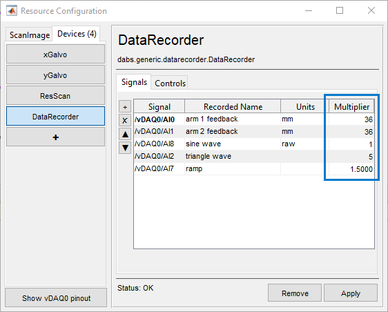
Signal Multiplier: a factor that is multiplied with the signal data to aid in linear conversions. Setting this as 1 leaves the signal unconverted.
Digital Trigger (Optional): a digital input to use as a trigger for the data recorder. Note that the trigger will only be used when the option Use Trigger is enabled (see below).
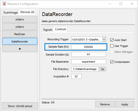
Sample Rate: The rate (Hz) at which to sample the analog inputs. The maximum rate is 500KHz and the minimum rate is 500 Hz.
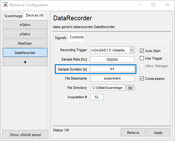
Sample Duration: The duration (seconds) to sample. When set at Inf, will continue sampling inputs until the data recorder is stopped. When set at a finite duration, will only record that duration and then stop. If using a trigger and Allow Retrigger is enabled, the recorder will record the specified duration again each time a new trigger occurs.
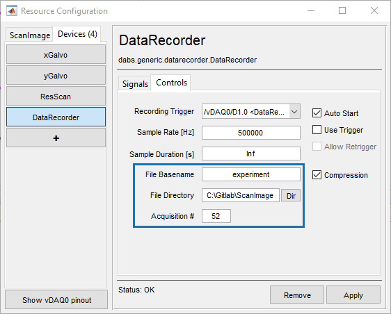
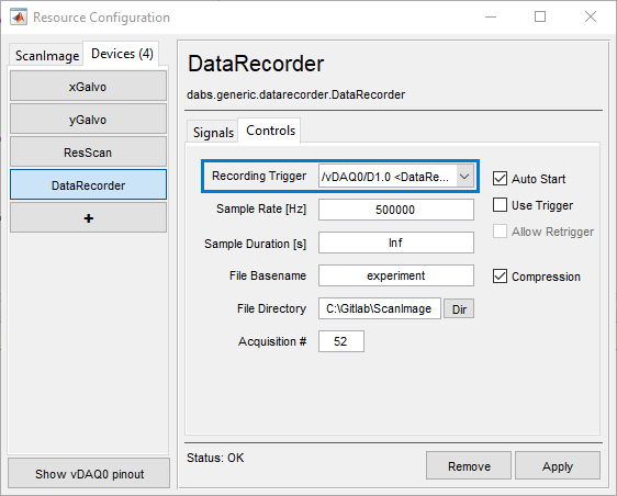
HDF5 File: The output file to save. The file name is combined from the File Basename and Acquisition #. The file is stored in the File Directory specified.
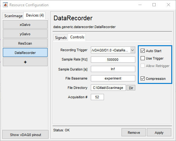
Auto Start: Whether to start/stop the Data Recorder when ScanImage starts/stops a grab.
Use Trigger: Whether to use the currently selected digital signal trigger, or to just start the data recorder immediately when the Start button is pressed.
Allow Retrigger: When a trigger is selected, whether to continue recording on subsequent triggers after the first trigger, or to stop after the recording of the first trigger only.
Compression: Whether to compress the output HDF5 files. Always useful when there’s a large amount of data being stored (e.g. a high sampling rate and long duration), as it can significantly reduce the hard drive space taken up in those scenarios. The compression algorithm is GZip and the DEFLATE parameter is 5.
Controlling the Data Recorder
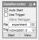
The Data Recorder is controlled with its widget on the sidebar. Various settings can be accessed here, as well as Start and View buttons.
The Start button starts the Data Recorder. Samples are recorded immediately if not using a digital signal trigger, otherwise the recorder will wait for the trigger before recording samples but will still be “active” awaiting the trigger. While the Data Recorder is active, the Start button will turn to Stop which will stop the recorder when clicked.
The View button opens a window which shows a snapshot of the current data captured by the Data Recorder. Not all of the history of the recorded data is available in this window, but the signals and their recent values can be seen here as a live sanity check. Data beyond a certain time in the past are only available in the HDF5 files that the Data Recorder produces.
Data Recorder HDF5 Files
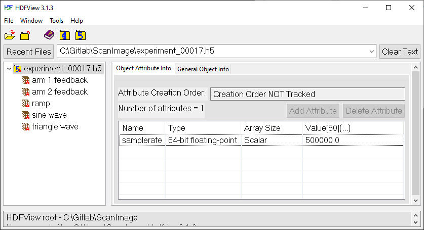
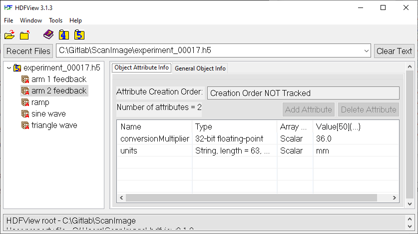
HDF5 files (.h5) can be opened using HDFView, where they can be also be exported into different formats.
The HDF5 file contains the datasets that were configured in the Data Recorder configuration table. Each dataset has two attributes, the conversionMultiplier and units that were defined in the resource configuration page.
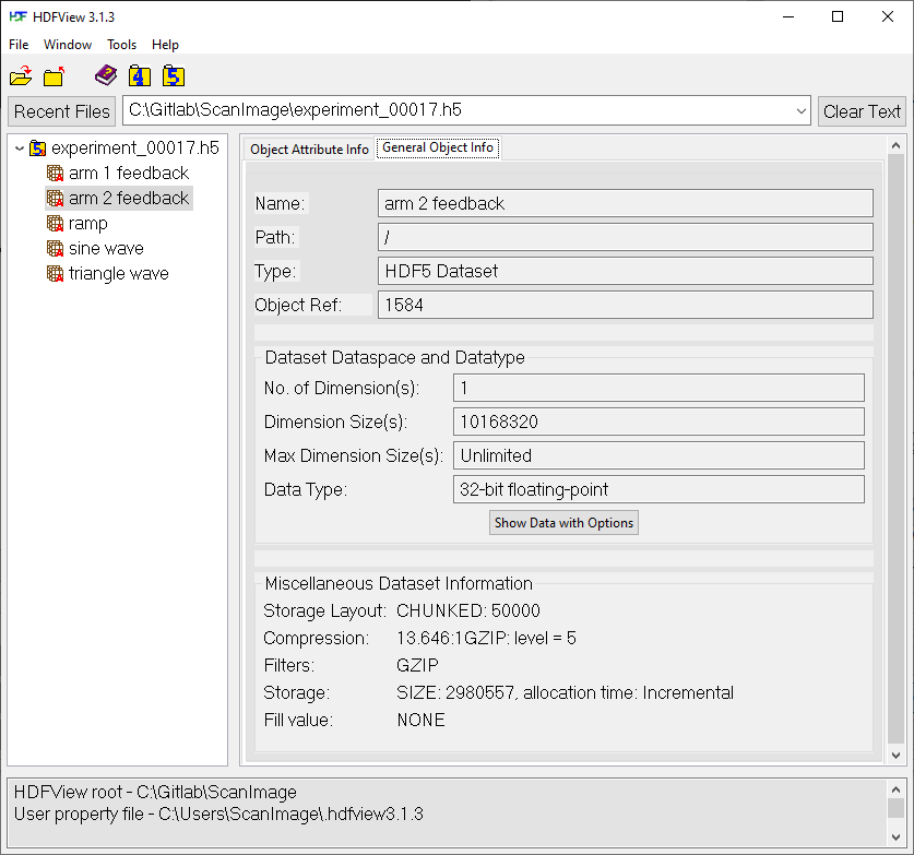
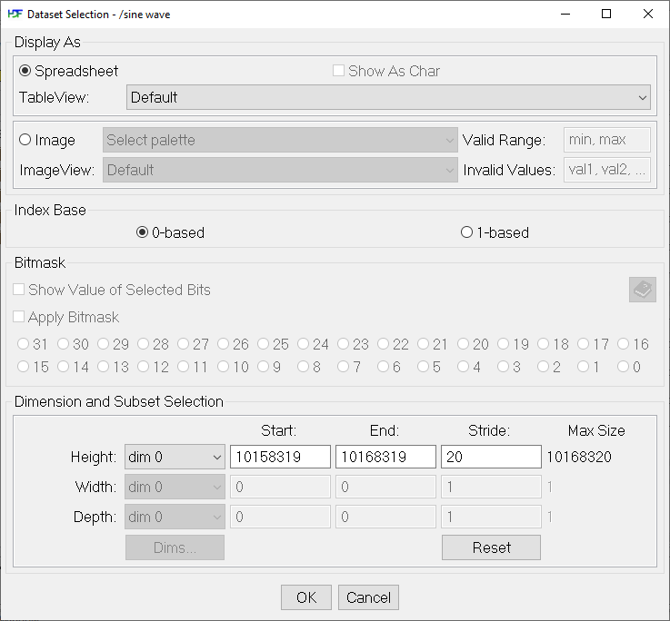
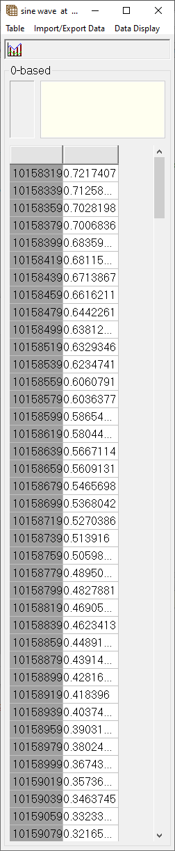
Each dataset contains the samples that were recorded by the Data Recorder. In the above dataset, there were 10,168,320 samples recorded. The data can be viewed in HDFView as a table, and different subsets of the data can be selected.
For example:
|
|
This operation displays every 20th sample on the last 10,000 samples.
The data can be used in Matlab via the Matlab HDF5 library. Commands like h5disp
can be used to view information about the HDF5 file and h5read can be used to
get the contents of the datasets into Matlab variables.
See Importing HDF5 Files in MATLAB for more information.