Newport Conex™ CC Stages
Hardware Config
Warning
Instructions here are no substitute for instructions that can be found in the product manual. Follow at your own risk.
The ScanImage® Conex™ CC driver supports single-axis linear and rotation stages from Newport which have the Conex™ CC Motion Controller.
The driver was developed and has been successfully tested with the Newport Conex-PR50CC rotation stage. These tests involved using the PR50CC rotation stage as a Motorized Half Wave Plate for slow-beam modulation.
Due to the common protocol shared between Conex™ CC stages, the ScanImage® Conex™ CC driver should work with any Newport Conex™ CC stage. But stages other than the PR50CC have not been tested directly with our team.
When connecting the stage to the ScanImage® PC via USB connection, the Conex™ CC Motion Controller will be recognized as COM port under the Ports (COM & LPT) section of Windows Device Manager:
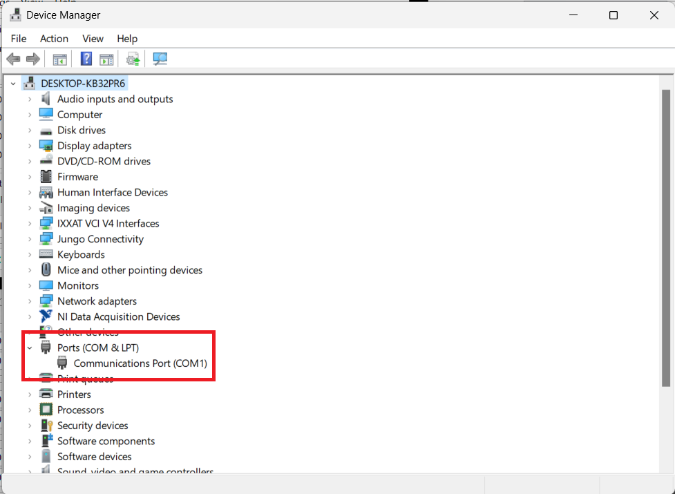
This COM port will be used to configure the ScanImage® Conex™ CC driver.
Note
Multiple single-axis Conex™ CC stages can be combined to create multi-axis stages. The ScanImage® Conex™ CC driver has not been tested in this fashion, but should support it as long as each stage axis has an independent USB connection with the computer. This can be condensed to one USB connection through a USB hub, which Newport recommends.
Software Configuration
In ScanImage®, open the Resource Configuration window from the startup dialog or from the Main Controls window under File>Configuration.
From the Resource Configuration window, click the “+” button. Select Motor Controller from the sidebar, and select ConexCC Linear Stage Driver. Assign a name and continue.
Configure the ScanImage® Conex™ CC driver.
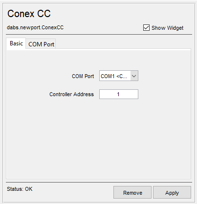
Serial Port |
Select the COM port assigned to the Conex™ CC device. |
Controller Address |
The controller address is usually set to 1. If a different address is provided by the manufacturer, use that instead. |
The advanced configuration settings can be accessed by clicking the COM Port tab in the Configuration window. These settings are specific to the COM port communication, and are dictated by the Conex™ CC manual. Usually, the default settings are sufficient. If your stage manual gives other values for Serial connection, they can be selected here. The default settings are taken from the Newport Conex™ CC Controller Documentation as of December 2023.
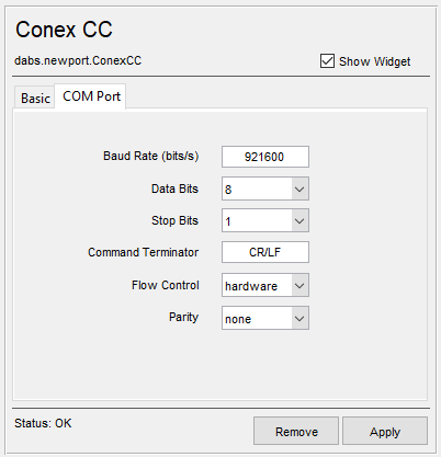
Baud Rate (bits/s) |
The baud rate of the serial connection provided in the stage manual. The Conex™ CC Controller Documentation specifies 921600 (default selection). |
Data Bits |
The number of Data Bits provided in the stage manual. The Conex™ CC Controller Documentation specifies 8 (default selection). |
Stop Bits |
The number of Stop Bits provided in the stage manual. The Conex™ CC Controller Documentation specifies 1 (default selection). |
Command Terminator |
The Serial Command Terminator provided in the stage manual. The Conex™ CC Controller Documentation specifies CR/LF (default selection). |
Flow Control |
The Serial Flow Control provided in the stage manual. The Conex™ CC Controller Documentation specifies Xon/Xoff, which is equivalent to “hardware” (default selection). |
Parity |
The Serial Parity provided in the stage manual. The Conex™ CC Controller Documentation specifies None (default selection). |
Once the device has been configured, it can be added to the ScanImage® imaging system via the left pane of the Resource Configuration window under the ScanImage tab after clicking the SI Motors button. This will reveal the Motor Controller configuration page, which will allow each independent Conex™ CC stage to be configured as a single axis.
Additionally, if the device is a rotation stage, it can be configured as a Motorized Half Wave Plate for slow beam modulation.