Acquisition Gating for low rep rate Lasers
Low rep rate (<10 MHz) lasers are common for applications such as 3-photon imaging. Capturing the fluorescence signal produced by such a laser requires important considerations. In a normal imaging regime, each pixel represents the mean fluorescence signal integrated over the dwell time of that pixel. When using a low rep rate laser, the signal consists of long empty periods between the laser pulses, consisting of only noise and zero useful signal. Including these empty periods in the integration will significantly reduce signal-to-noise ratio (SNR). ScanImage has the ability to apply a sampling window with respect to the laser pulse, allowing the empty region between laser pulses to be ignored. This increases SNR by omitting the unnecessary noise regions from the data analysis. This feature can be used in both resonant and linear scan modes for both vDAQ and NI DAQ hardware.
In general, use of this feature involves wiring the laser clock to an input of the DAQ, acquiring PMT data in a display that plots it over time in ticks of the sample clock from one laser pulse to the next, and then drawing a window around the portion of the signal that fluorescence signal is anticipated to occur. See below for details on configuring ScanImage to do all of this.
On the vDAQ
This differs a little based on whether using the standard or high speed vDAQ.
Standard vDAQ
Synchronizing the sampling rate to the laser rep rate can be beneficial by reducing jitter, but is not a requirement with the standard speed vDAQ.
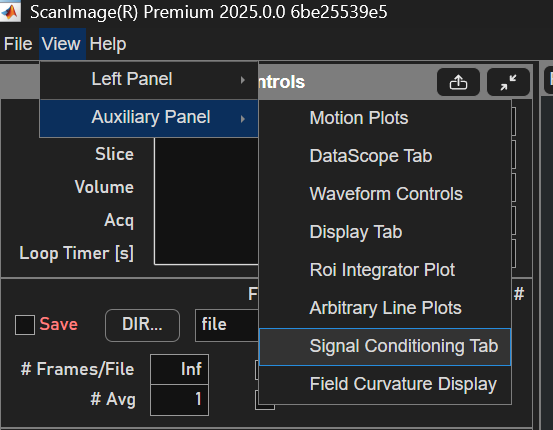
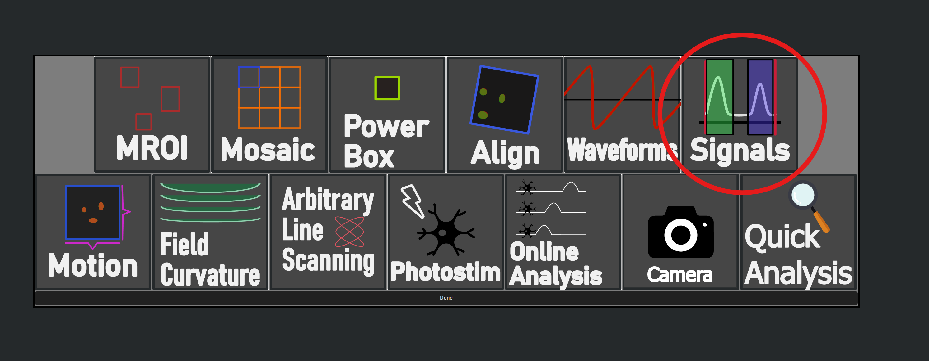
First, open the Signal Conditioning Controls which is located in the Auxiliary Panel. This can be done either from the top left of the ScanImage GUI via View > Auxiliary Panel > Signal Conditioning Tab, or by selecting the ‘+’ button in the Features Tab and selecting ‘Signals’.
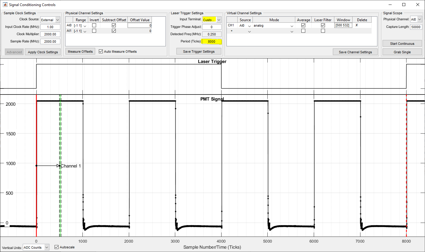
In the Sample Clock Settings, select ‘External’ under the Clock Source. In the
Laser Trigger Settings panel, specify the port that should be used for laser gating
in the Clock Input Terminal field.
If synchronizing sampling to the laser rep rate signal, use the CLK IN port. Otherwise, the
laser rep rate can be configured for use on any of the digital inputs on the vDAQ breakout.
Note that using the vDAQ breakout DIs as a clock input is unavailable on the high-speed vDAQ.

Next, observe the Virtual Channel Settings table.
Physical channels can now be assigned to virtual channels arbitrarily.
From the Source column, select physical ports which should receive
signals that should be gated relative to the laser.
Next, place a check in the Laser Filter column for those rows.
Next, from the Signal Scope panel, specify the Physical Channel
and a Capture Length greater than (4 x sampling rate / laser frequency),
then click Start Continuous. This will start displaying the PMT signal in the PMT Signal window.
If the Clock Source selected is ‘External’, the laser clock will be displayed above the PMT Signal window
and a frequency will be detected and displayed from the
Laser Trigger Settings panel.
You can start a FOCUS acquisition now. It is advantageous to use a very large capture length as the PMT data for several laser pulses are
displayed overlapped on the PMT Signal display. This way, if the sample has just few fluorescing regions, you have a greater chance of
seeing the fluorescence spike plotted. You can now set the laser gating window so that it envelops just where fluorescent spikes are expected
to occur. This is done through the window column or through clicking and dragging the window in the PMT signal plot.
In the PMT signal plot, you can click the middle of the window to drag it, or you can click and drag the edges of the windows to only change the start and end of the window.
You should find that narrowing the window to just the fluorescent peak greatly improves the imaging quality.
High Speed vDAQ
With the high speed vDAQ, there are a few additional steps and alterations.
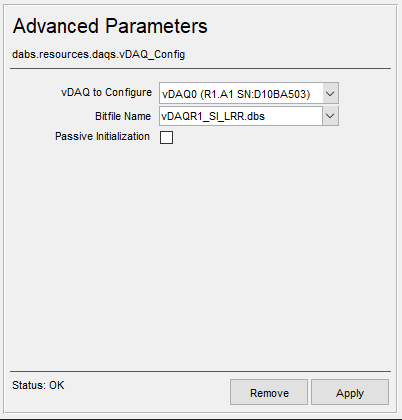
First, add a vDAQ Advanced Parameters device from the resource configuration window.
This can be found under the Vidrio devices.
Select the vDAQ to configure and then select the Bitfile Name vDAQR1_SI_LRR.dbs,
then click apply.
Now, the directions for the standard vDAQ can be followed, with the exceptions that:
The vDAQ sampling rate **must** be synchronized to the laser repetition rate
In the event of using a sub 1MHz clock (e.g. 250 kHz) that has been externally multiplied to a frequency the hardware can support (>=1MHz), the laser trigger settings
Input Terminalfield can be set toCustom Clockto configure the FPGA to synchronize to the true clock rate.For example, if 250 kHz was multiplied by 4 using an external AD9516 evaluation board to 1MHz, the input clock rate can be set to 1MHz and the clock multiplier can be set to 2000 to accomodate the 2GHz sampling rate.
Then, the
Custom Clockmultiplier can be configured to adjust to the true clock rate:2e9 / 250e3 = 8000. When entering 8000 into the custom multiplier field, the FPGA manually synchronizes to the correct 250 kHz frequency.
On National Instruments hardware
The first step to using this feature is to set up the hardware. This involves wiring the laser clock output from the laser to the DAQ equipment.
Note
For either resonant scanning or linear scanning, this requires a FlexRIO FPGA-based acquisition DAQ as described here.
For resonant scanning, this requires the NI SCB-19 digital breakout plugged into the front of the digitizer. The laser clock signal should be wired into any of DIO0.0-DIO0.3. For linear scanning the clock can be connected to any PFI line of the Auxiliary Digital I/O DAQ.
Note
Optionally, the digitizer can be synchronized to the laser clock. This can further improve SNR by reducing jitter. The laser clock must first be multiplied to a rate high enough for the digitizer (20 MHz - 80 MHz for the 5732, 50 MHz - 120 MHz for the 5734). This can be done using external clock synthesizing circuits. More details about laser clock synchronization can be found here.
Once the laser clock is selected, the settings in the Machine Data File must be updated accordingly. Launch the Machine Configuration Editor by launching ScanImage® and clicking ‘Modify’ on the startup window. Go to the Scanner Settings page and click the ‘Advanced’ button at the bottom. A setting for specifying the laser clock port will appear. Indicate the port where you connected the laser clock.
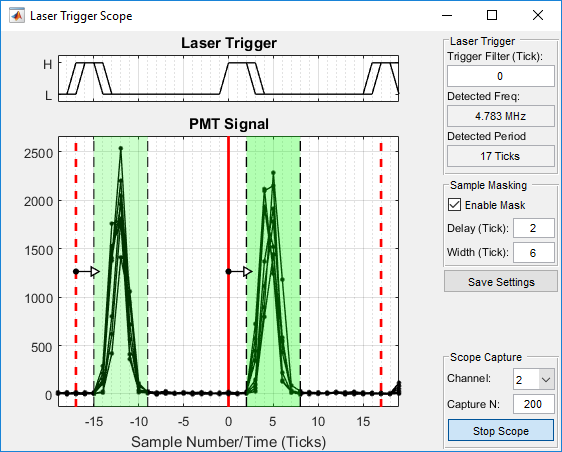
At this point, you are ready to start scanning. Launch ScanImage® and start imaging a sample. To configure the sampling window, open the Laser Trigger Scope from the view menu on the MAIN CONTROLS GUI. This tool will allow you to see the PMT signal response to laser pulses in real-time. To get started, click “Start Scope”. You should now see live updating signal traces. The “Detected Frequency” indicator should show the correct laser frequency. If you do not see any live data and/or the frequency is missing or wrong, verify wiring and the correct Machine Data File setting. If jitter is observed in the Laser Trigger trace, try increasing the Trigger Filter value.
To enable the sample masking, check the “enable mask” checkbox. Drag the green window to specify what samples should be included in pixel integration. Drag the edges to change the width of the window. If you are actively imaging, you should see the effect of the settings in the channel window in real-time. Once you are happy with your settings, click the “Save Settings” button. The settings are saved to the machine data file.