Waveform Optimization
Command Waveform Optimization
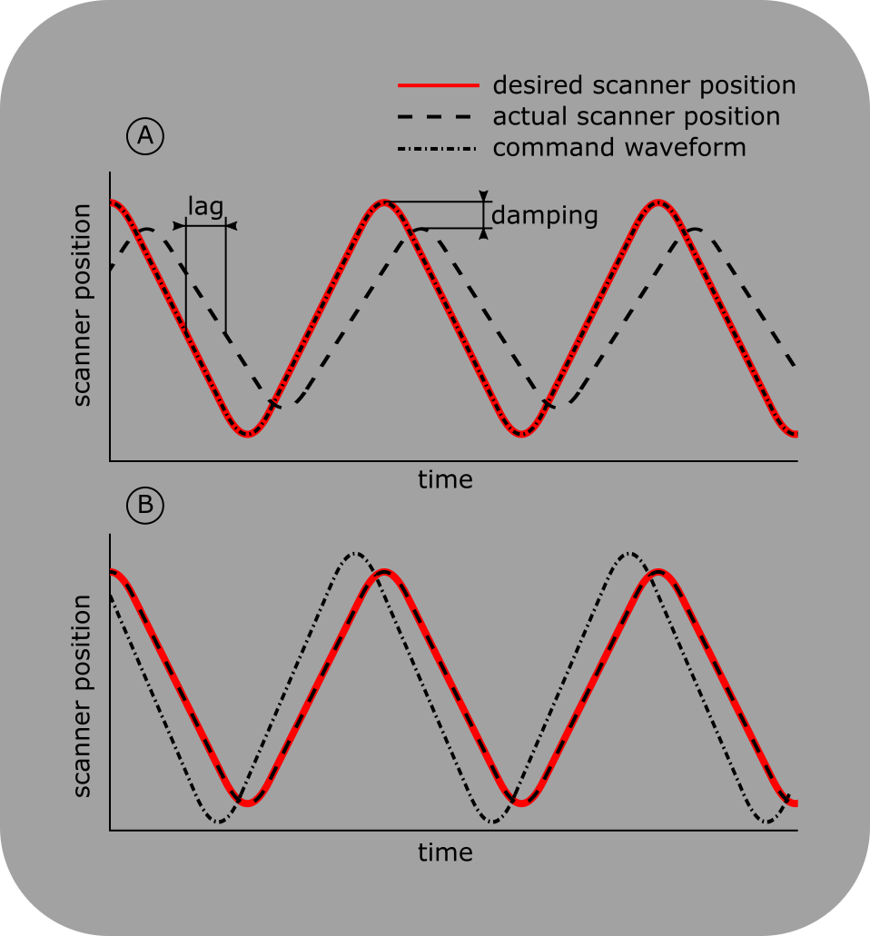
When controlling a scanner with an analog command waveform, scanner lag and damping result in a tracking error (A). This results in warped image geometry for frame scanning and an incorrect trajectory for line scanning. ScanImage® can automatically optimize the scanner command waveform to minimize the tracking error (B).
ScanImage’s advanced imaging modes (Arbitrary Line Scanning, Multiple Region of Interest (MROI) Imaging) rely on accurate positioning of the involved scanners (Galvos, piezos/voice coils). These scanners ship with controllers that implement simple PID loops to ensure tracking accuracy. However, these controllers cannot fully compensate for the dynamic behavior of the scan system, such as system lag and mechanical damping. These effects accumulate in a tracking error, which can result in a warped image geometry for frame scans, and an incorrect trajectory during line scans. To compensate for the tracking error, ScanImage® can optimize the scanner command waveform using Iterative Learning Control.
During the optimization, ScanImage® sends a command waveform to the scanners, measures the position sensor feedback of the scanner, and updates the command waveform based on the calculated tracking error. This process is repeated iteratively until the tracking error is within an acceptable range.
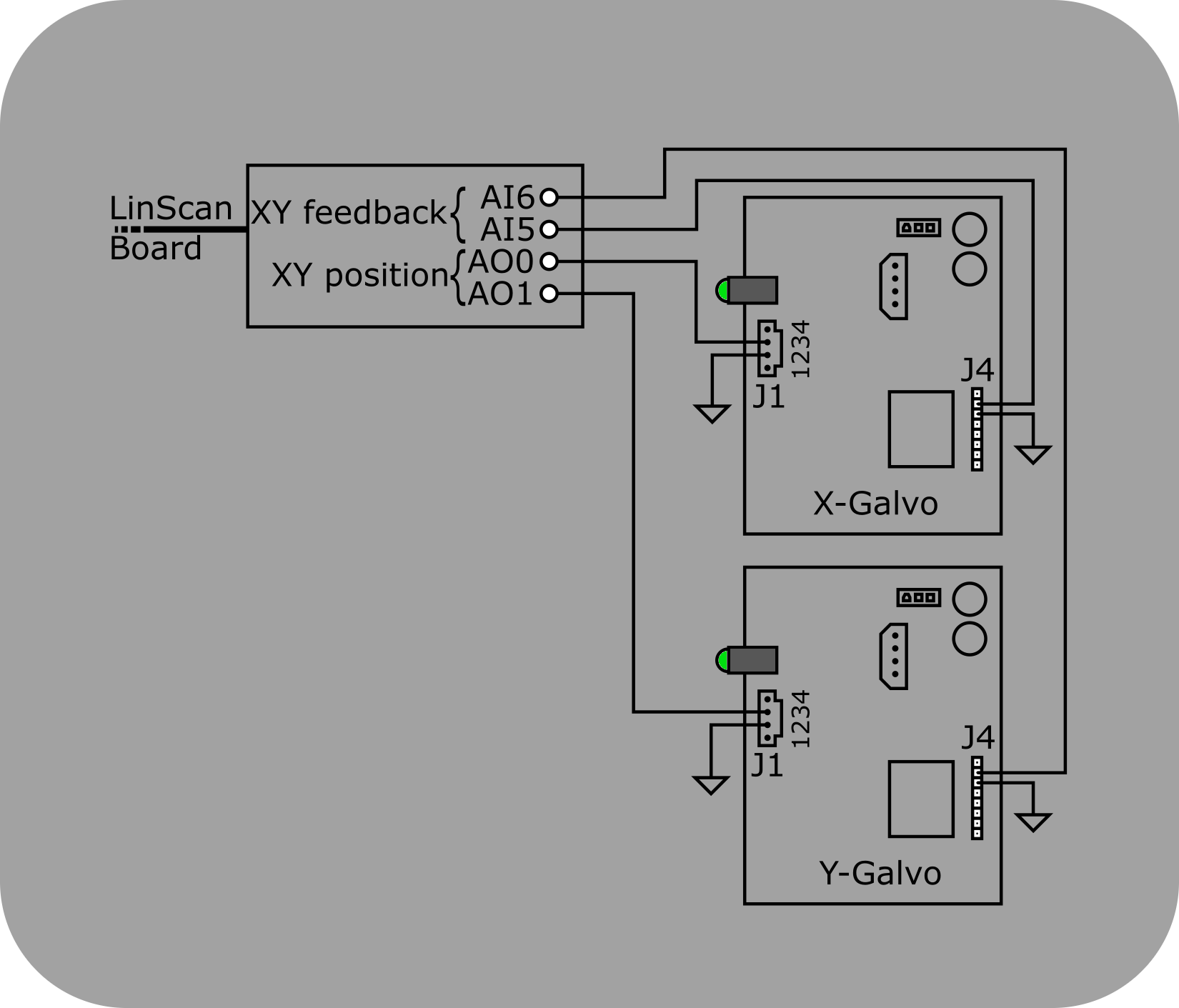
Galvo scanner position sensor wiring
The Cambridge Technologies 671 series galvo controller boards expose the sensor feedback on pin J4.2.
Wiring
The command waveform optimization feature requires a connected position feedback sensor for each scanner. This section describes how to set up the feedback sensors for commonly used scanner controller boards.
Cambridge Galvo mirrors
The galvo position and offset inputs are located on connector J1 of the Cambridge Technologies 671 series galvo controller board. Assuming these inputs are configured to be non-inverting single ended (W4 1-3 and 4-6 jumpered), the following wiring scheme can be used:
Pin |
Signal |
MDF Section |
MDF Variable |
Recommended MDF Value |
J1.2 (X,Y) |
Signal GND |
|||
J1.3 (X) |
X Galvo position |
LinScan / ResScan |
XMirrorChannelID / galvoAOChanIDX |
0 |
J1.3 (Y) |
Y Galvo position |
LinScan / ResScan |
YMirrorChannelID / galvoAOChanIDY |
1 |
J4.2 (X) |
X Galvo position feedback |
LinScan / ResScan |
XMirrorPosChannelID / galvoAIChanIDX |
5 |
J4.2 (Y) |
Y Galvo position feedback |
LinScan / ResScan |
YMirrorPosChannelID / galvoAIChanIDY |
6 |
J4.3 (X,Y) |
Signal GND |
Fast-Z
Wire the controller’s position feedback signal to the DAQ terminal defined in the Machine Data File variable ‘fastZAIChanID’.
Note
The analog feedback sensors might use different scaling factors than the command outputs. After wiring the signals, open the Waveform Controls window, select ‘Update Waveforms’, and calibrate the feedback for each scanner.
Operation
Before starting a scan, open the Waveform Controls window and select ‘Update Waveforms’. The checkbox ‘Optimized’ indicates if ScanImage® has previously performed an optimization for the current command output. In this case, the optimized waveform will be used for the scan. In case there is no optimized waveform in the ScanImage® cache, choose ‘Optimize’ to start an optimization run.
Note
The Cambridge 671 galvo control boards are designed to prevent physical damage to the galvos. If the galvos are driven too hard, the boards can pause the galvo motion. In this case, the scanner optimization will fail, and you must choose scan settings that reduce the maximum velocity / acceleration of the galvos before retrying an optimization run.
Warning
ScanImage® does not limit the scanner velocity / acceleration during the optimization process. While the scanner control boards should prevent physical damage to the scanners, Vidrio does not assume any liability for damages due to overdriving scanner components.
Advanced
In ScanImage 2025, two new user-settable properties have been introduced for finer control over waveform optimization: the number of waveform signals to test, and the moving window size.

Number of Signals
When ScanImage optimizes the output waveforms, it sends the desired waveform to the paired device (for example, a galvo) and measures the feedback. The feedback indicates how well the device actually followed the command waveform. Then, the feedback is run through an optimization function and optional averaging before the process is repeated.
The number of signals is how many waveforms are sent to the device per iteration. Increasing this number may yield a more accurate command waveform. However, more waveforms will increase the optimization time.
Moving Window Size
Using a moving average may be helpful to reduce noise in command waveforms. Given an array of numbers, this works by averaging a particular value with the numbers to the left and right of it.
By default, the moving window size (measured in ms) will perform no averaging. The formula to determine the number of points to average is:
points = round(ControlSampleRate * movingWindowSize / 1000)
The larger the window size, the more surrounding samples will be averaged into each sample, effectively smoothing the command waveform. In most cases, either averaging is not needed or a little averaging (using a small window size) may reduce command waveform noise.
API
ScanImage® ships with two default optimization algorithms, which are located in
+scanimage\+mroi\+scanners\+optimizationFunctions
Name |
Used for |
Comment |
deconvOptimization |
Galvos |
fast convergence, relies on linear scanner behavior |
proportionalOptimization |
FastZ (piezos) |
slower convergence, can optimize non-linear systems |
The functions take the desired waveform and the current scanner feedback as an input, and generate an updated command waveform based on the tracking error. These functions are called iteratively until the output ‘done’ equals true. Data can be passed in between calls by using the variable ‘optimizationData’.