SLM Photostim Calibration and Alignment
Phase LUT Calibration
SLMs take pixels from bitmaps and convert them to phase shifts. Ideally, each pixel’s phase shift would map linearly from 0 to 255. In reality, we must determine the actual relation.
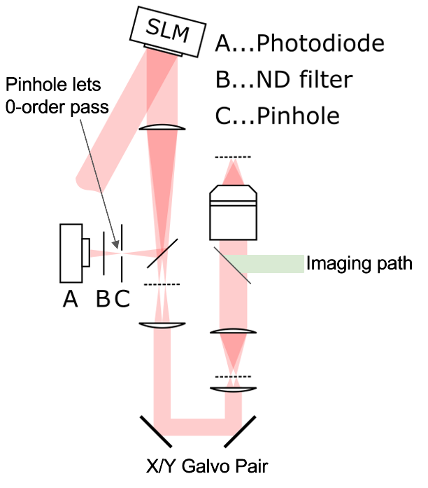
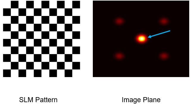
To calibrate the phase mask, a checkerboard phase mask pattern is applied to the SLM and every other checker square is swept through pixel value range [0, 255] while the others are held constant. At the same time, the intensity of the zero order spot is measured with a PMT as energy is diverted to higher order spots. The largest swing in measured zero order intensity while sweeping pixel values is used to map pixel values to phase.
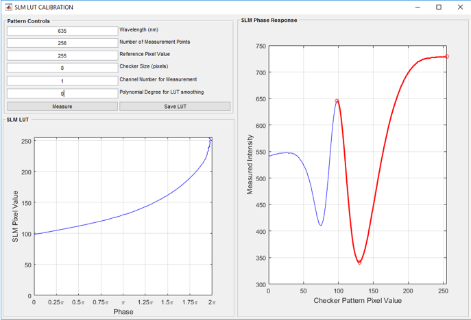
Wavelength (nm) |
The wavelength of the stimulation laser |
Number of measurement points |
The total number of total phase masks from the checkerboard pattern mask to the zeroed phase mask |
Reference Pixel value |
The 8-bit value of the checker squares whose phase remains the same throughout |
Checker Size Pixels |
The side length of each of the checker squares |
Channel number for measurement |
The PMT Channel that should be used for measuring the brightness of the zero order spot |
Polynomial Degree for LUT smoothing |
A polynomial curve can be fitted to the SLM Pixel Value vs Phase plot. A value of zero gives no polynomial fitting. |
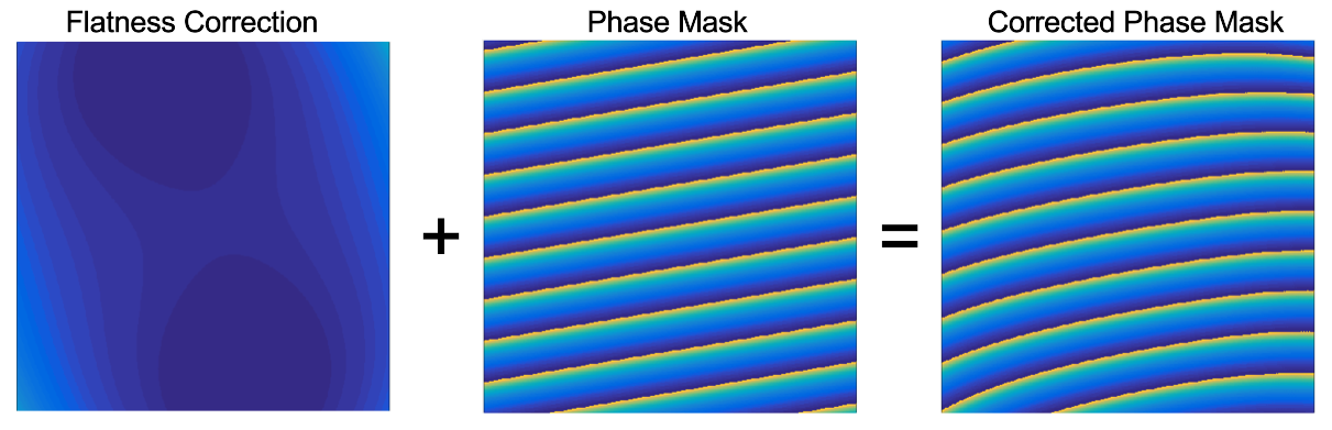
SLM Flatness Correction
Wafer polishing of the SLM introduces a slight dome shape. To correct for this, a flatness correction file is provided by the manufacturer. The correction is wavelength dependent.
Align Linear Scanner to Imaging
If a linear scanner is paired with the SLM scanner, follow the alignment page to align it to the imaging scanner.
Laterally Align the SLM
This step is very similar to the Stage-Scanner Alignment, except instead of moving the sample with the stage, you offset the steered beam with the SLM.
Follow the prompts to laterally align the SLM.
Align SLM Z to stage Z
This step is very similar to fastZ alignment, except instead of offsetting the focal plane with the fastZ device, you offset the focal plane with the SLM.
Laterally Align the SLM through Z
The FOV may shift laterally while traveling through Z. Clicking the checkbox in the upper-left corner of the Z-alignment window reveals a lateral alignment GUI which can be adjusted at each calibrated SLM Z point in the Z alignment window.
Note
There is no need to click a save button before moving on to the next Z point.