Photostimulation
ScanImage® features a photostimulation module. If your microscope has two independent scan heads, they can be used for simultaneous and independent imaging and photostimulation.
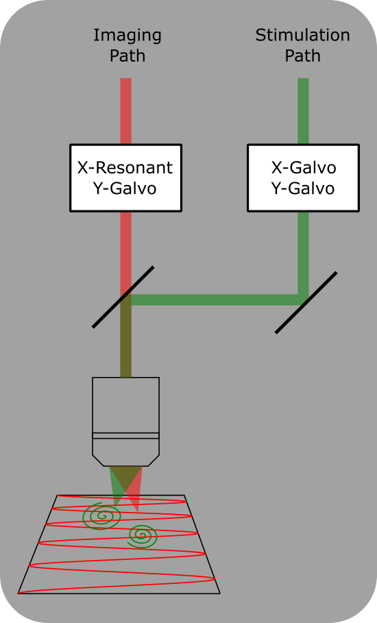
Dual Scanheads
Dual Scanhead setup for ScanImage. Two independent scan heads allow for simultaneous imaging and photostimulation. A dichroic mirror combines the two scan paths into the same objective.
The photostimulation module allows you to:
Define multiple stimulus groups and independently trigger them
Built in editor to set up stimuli and timing
Built in Cell picker GUI for for semi-automatic or manual cell segmentation
Live monitoring of delivered stimuli and power
Photostimulation Requirements and Capabilities
Hardware Requirements
The microscope configuration must include:
A galvo control board, which is either:
A Vidrio vDAQ
A National Instruments X-series DAQ
A Pockels cell (for laser power control)
The stimulating scanhead may be:
A galvo-galvo scanhead
A resonant-galvo-galvo scanhead (the resonant mirror stays fixed)
A resonant-galvo scanhead cannot be used for photostimulation. However, it may be used to image during (for dual scan paths) or between stimulations. Power boxes may be helpful in controlling where one is imaging in this cases.
Photostimulation is supported for both single and dual scan path microscopes.
A microscope with a single scan path can use the photostimulation module, but stimulation cannot happen simultaneously with imaging. Imaging must be aborted before stimulating, then can be resumed after the stimulation is complete.
Photostimulation with dual scan paths allows for simultaneous imaging and stimulation with complete spatial and temporal independence. Accurately targeting cells for stimulation using a dual path microscope requires precise alignment between the imaging systems. For this follow the procedure outlined in the Alignment page: This step ensures accurate registration between imaging and stimulation. This step is only needed when using dual scan path microscopes.
Not a requirement, but a strong recommendation for dual scan path photostimulation is that the stim and beam output triggers are configured and looped back into the imaging scanners’ auxiliary input trigger terminals. This allows each of the stimulation events to be timestamped in the metadata of the acquired TIFF file when imaging. For vDAQ based acquisition systems in ScanImage 2023.1.0, the stim and beam output triggers can be shared with the imaging scanners’ auxiliary input trigger terminals without the need for routing with a BNC cable - they can simply share the same digital output. It would be a default configuration to always have the stim and beam output triggers routed to the imaging scanners’ auxiliary input trigger terminals 3 and 4, but users may need those auxiliary inputs for other purposes. Instead, the use of the stim and beam output triggers remains optional, but the user must consciously decide this.
Configuration
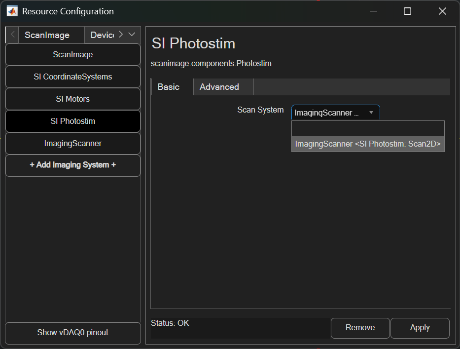
ScanImage requires a galvo-galvo, resonant-galvo-galvo, or SLM scanner system (AKA imaging system) to be paired with it. One can be created by adding an Imaging System from the Resource Configuration window.
Once added, it can be paired to the photostimulation module from the SI Photostim resource page. In ScanImage 2025, the photostimulation module’s imaging scanner can be updated while ScanImage is active.
The advanced panel can be used to configure extra features included with Photostim.
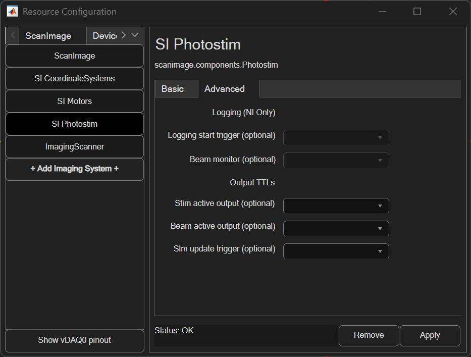
Logging
When simultaneous photostimulation and imaging is enabled, the galvo/beam feedback can be logged to file.
Logging start trigger |
The logging start trigger can be configured to an analog input port. When a rising edge (TTL) is received on that port and logging is enabled, so that collection of stim scanner galvo X, galvo Y, and beams analog input data
|
Beam monitor |
If logging is enabled, beam monitor sets the analog input that will be used to measure modulated laser power. If this is left unset, the monitor task will use the stim scanner’s paired beam’s configured feedback port instead. |
Output TTLs
Various output TTLs can be configured to track event timing, like when a stimulation ROI group is executed.
Stim active output |
Configure this port to output a TTL high when a stimulation ROI Group is being executed and low at all other times |
Beam active output |
Configure this port to output a TTL high when any paired stim beam device is modulated to a nonzero power and low at all other times |
Slm update trigger |
Configure this port to output a TTL high pulse when the executing the stimulation roi contains SLM stim points |
Create Stimulus Groups
Stimulus groups are a special kind of ROI group that define a parametric path instead of a 3D volume. A stimulus group is comprised of multiple ROIs that define a continuous sequential laser path. Multiple groups can be defined and stored in the Photostimulation tab. Once the groups are defined, the Triggering Stimulus Groups section describes how to stimulate with them.
To setup stimulus groups, open the Photostim Tab.
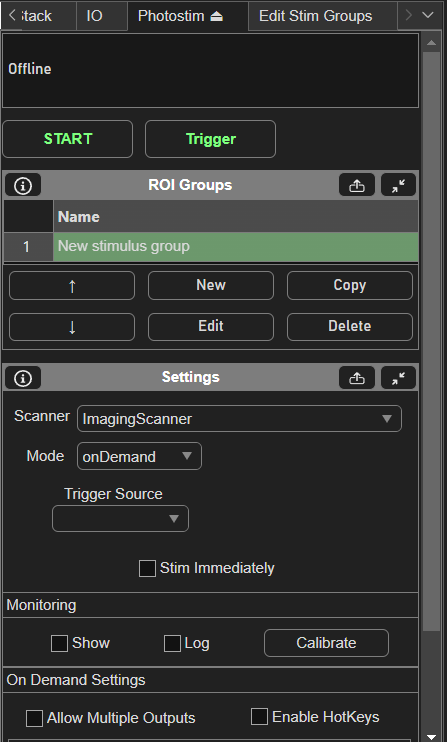
Then, create a new stim group by clicking the New button under the ROI Groups GUI. Clicking Edit with the new stim group highlighted brings up the Edit Stim Groups Tab.
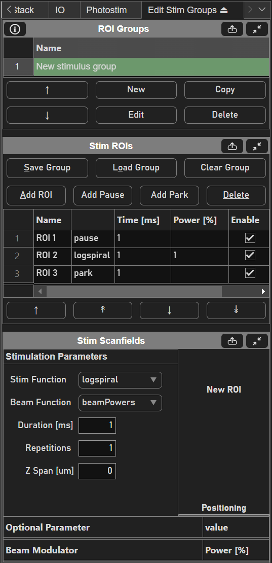
Stimulus groups allow complete freedom in designing the path for the laser to take. Best practices should be followed to ensure desired results. A stimulus pattern is comprised of a sequence of stimulus functions, each of which can be parameterized with position, size, rotation, laser power, number of repeats, parametric function, and custom parameters for the parametric function. The stimulus function can be chosen from a set of built in or custom stimulus functions. Below is a description of each built-in stimulus function.
Built-in Stimulus Functions
Pause |
A pause indicates a delay time between two stimulus functions in order to allow the scan mirrors time to transition from the previous stimulus function to the next; Laser is always blanked during this function |
Park |
Moves the scan mirrors to the park position (specified in the MDF) in the specified time duration; Laser is always blanked during this function |
Point |
Moves the scan mirrors to the specified position and stays there with the beam exposed to the desired power for the specified duration |
Way Point |
Makes the scan mirror path pass through but not stop at the specified position; the beam is exposed to the desired power for the specified duration as the scan mirrors pass through the specified point |
Line |
|
Circle |
|
Log Spiral |
Spiral pattern starting with the laser at the center and spiraling out.
|
Sine Square |
Back and forth sweep of the laser across a square region
|
Hypotrochoid |
|
Hypocycloid |
|
Cardioid |
|
Musoid |
A typical stimulus pattern begins with the laser at the parking position to minimize exposure of the sample to laser light (even with the pockels cell blanked). Time must be given to allow the laser to travel from the parking position to the first cell (or ROI) to stimulate. A parametric stimulus function can then be chosen for the given cell with parameters such as laser power and duration. Finally, the laser should be returned to the parking position. Thus, A stimulus group to stimulate one cell would have three ROIs:
Pause function
Stimulation function (ex: logspiral)
Park function
If it is desired to stimulate multiple ROIs in one pattern, a pause should be inserted between stimulations to allow transition time, i.e.:
Pause function
Logspiral function
Pause function
Sinesquare function
Pause function
Logspiral function
Park function
The pauses between stimulations are important because the galvos require time to travel between ROIs. Without the pauses (or if the pauses are too short), the pockels cell will be open while the galvo is still traveling to the desired ROI, causing light exposure to the wrong part of the sample. If too large of a change in position is commanded without adequate transit time, or if the stimulus pattern is too demanding of performance from the galvos, the galvo controller may reset, causing a momentary loss of galvo position control. It is therefore important to carefully design the stimulus pattern to avoid this, and test the pattern to make sure the results are desirable. The best way to test for desired results is using the monitoring and logging feature to verify proper response from the galvos.
Triggering Stimulus Groups
Once stimulus patterns have been defined, the ScanImage® Photostimulation module provides two modes of operation for commanding the stimuli.
Sequence Mode: Output of stimulus patterns in a prescribed order. This is the best option if you know before hand the order that you want to output stimulus groups and you desire a high level of timing precision for the triggering of stimulus output
On-Demand Mode: Random access output of any stimulus pattern at any time. This option is best for experiments that need the flexibility to select which stimulus to output during the experiment in response to experimental conditions
Trigger Outputs:
I/O Port |
Signal |
|---|---|
port0/line0 |
Photostimulation active (goes high 1ms before the Pockels cell opens, stays high until stimulus group is completed.) |
port0/line1 |
Laser active signal (Pockels cell is open) |
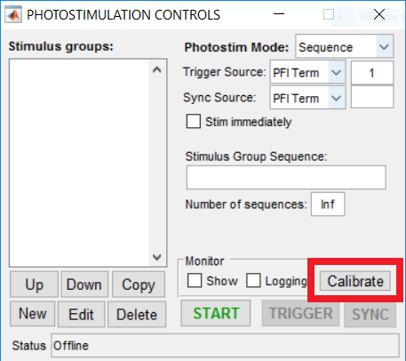
Sequence Mode
Sequence mode for ScanImage® Photostimulation allows output of stimulus patterns in a prescribed order. When the experiment starts, every time a trigger arrives, the next group in the sequence is output. The trigger can come from software or a digital pulse. Using a digital pulse allows a high level of timing precision to synchronize the stimulation with external events. The following screenshot shows an example of the setup of a sequence mode experiment:
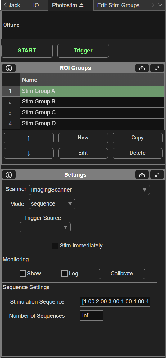
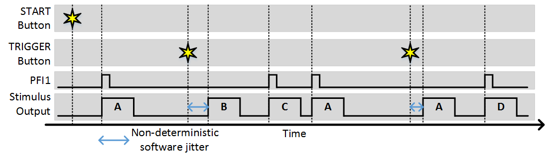
In this example, 4 stimulus patterns have been designed using the Edit Stim Groups tab. The Stimulation Sequence of “1 2 3 1 1 4” specifies the order that groups will be output. In this case, groups 1, 2, and 3 will be output, then group 1 twice, then group 4. The “Stim immediately” option specifies whether or not the first group will output immediately when the experiment is started. With this option disabled, no output will happen immediately when the experiment starts, as the first output will wait for a trigger. The “Trigger Source” specifies the terminal where digital triggers are accepted. The number of sequences specifies how many times the sequence can repeat. If set to infinite, the experiment will continue until aborted. The following figures shows an example of what will happen during the experiment.
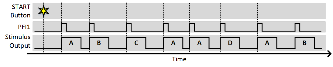
As you can see, each trigger causes the next stimulus to be output. Since the number of sequences is greater than 1, after the sequence completes it starts again from the beginning. The next example shows what would happen is “Stim Immediately” was on:
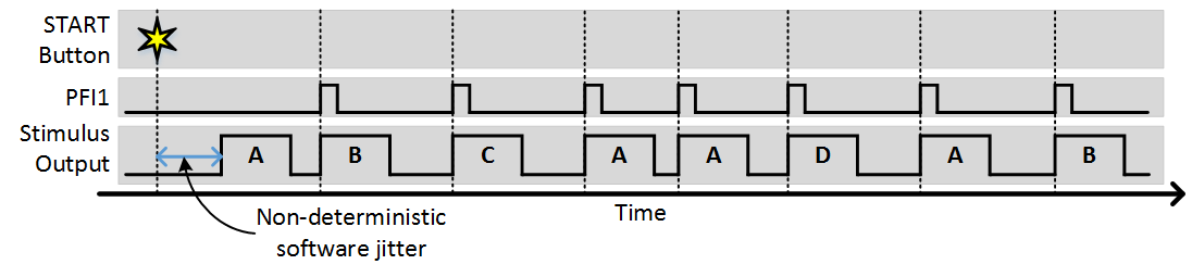
The only difference is that the first stimulus pattern in the sequence was output immediately without waiting for a trigger. All subsequent outputs were then triggered. In this case the time from when the start button is clicked to when the output starts is non deterministic, as software operations such as computing and loading the analog output signals for the scanners.
The stimulus patterns can also be triggered from software by clicking the trigger button (or using the command line API). Software triggers are inherently non-deterministic so this should be taken into consideration. The following example shows the experiment with “Stim Immediately” off and a combination of software and external triggers.
Synchronization
ScanImage® Photostimulation includes a “sync” option if it is desired to ensure that stimulus output always starts synchronized to an external signal. A common example of this is if you always want the start of stimuli to coincide with the start of an imaging frame.
Note
Synchronizing photostimulation to an external signal is only supported using NI hardware.
To utilize the sync function, set the Sync PFI terminal to the source of the sync signal. With this set, whenever a software or external trigger arrives, the stimulus output begins with the next sync signal. The following example shows the same experiment where the sync terminal is set to PFI2 and the imaging frame clock is wired into this terminal:
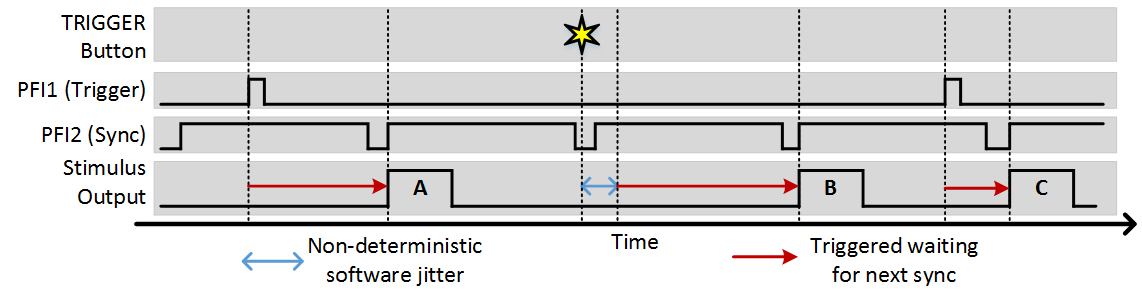
You can see that in this example, the sync option ensures that regardless of when a trigger comes, stimulus output always starts at the beginning of a frame. The software trigger still incurs some jitter to when the trigger is registered, but once registered the next output still occurs synchronously with the sync signal.
On-Demand Mode
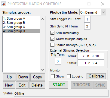
On-demand mode for ScanImage® Photostimulation allows output of stimulus patterns in a random access fashion. Any pattern can be immediately commanded at any time. This allows a high level of experimental flexibility but at the cost of some determinism. Unlike sequence mode, since the next stimulus to be output is not known beforehand, at the moment when a stimulus is commanded there is a non-deterministic delay associated with loading the desired stimulus into the analog output buffer and triggering it. This delay is dependent on factors such as the size of the stimulus pattern and the performance and current load on the CPU and typically is on the order of 1-100 ms. The following screenshot shows a simple setup for on-demand mode:
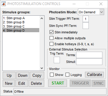
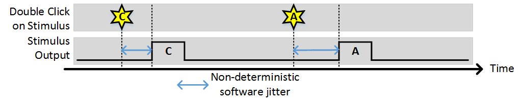
In this case four stimulus patterns have been defined. When the “START” button is clicked, the photostimulation module goes into active mode where it is waiting for the user to request a stimulus. This can be done by double clicking the desired stimulus in the list on the left (or via the command line API). If the “Stim immediately” option is on, the stimulus is output immediately (with some non-deterministic delay). If “Stim immediately” is off, the stimulus is loaded into the analog output buffer, the waits for an external or software trigger. If allow multiple outputs is on, once a stimulus is commanded it can be triggered multiple times. The following examples show behavior with the various selections for these options.
Stim Immediately: ON, Allow multiple outputs: OFF
Stim Immediately: OFF, Allow multiple outputs: OFF
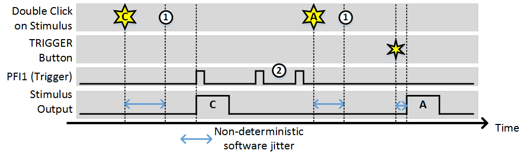
In this example, (1) indicates the time points where the buffer has been loaded and the output is awaiting a trigger. While the time it takes to load the buffer is non-deterministic (and triggers that arrive during this time are ignored) once the buffer is loaded the stimulus starts deterministically with the next trigger. Note, the triggers indicated by (2) were ignored because since “Allow multiple outputs” is off. A stimulus can only be triggered once after being commanded.
Stim Immediately: OFF, Allow multiple outputs: ON
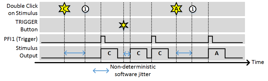
As with the last example, (1) indicates the time points where the buffer has been loaded and the output is awaiting a trigger. Since “Allow multiple outputs” is on, once a stimulus is commanded it can be triggered for an unlimited number of outputs. It stays loaded in the analog output buffer until a different stimulus is requested.
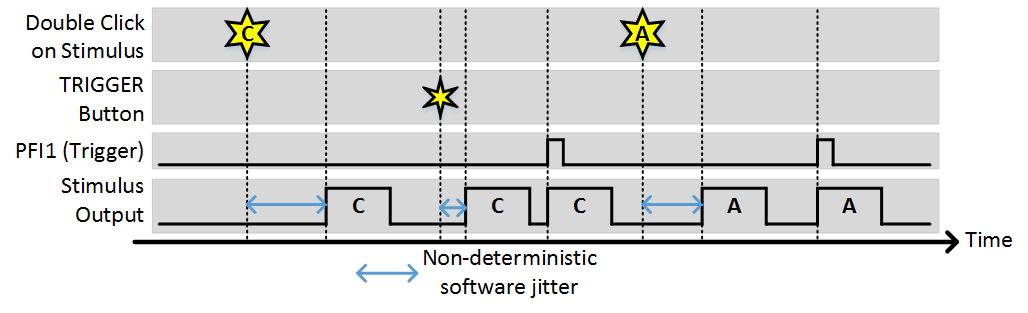
Stim Immediately: ON, Allow multiple outputs: ON
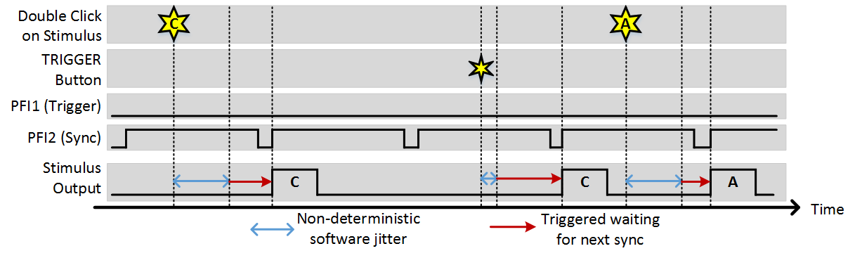
Synchronization
Just as with sequence mode, a synchronization signal can be used to align the start of any stimulus with an external source. A common use case of this is if you always want the start of stimuli to coincide with the start of imaging frames. The following is an example of functioning with a sync signal.
Stim Immediately: ON, Allow multiple outputs: ON, Sync PFI Terminal: PFI2 (frame clock wired in)
Hot-Keys
When using on-demand mode, hot keys can be enabled for faster access to commands. When the photostim module is active, with the hotkey option enabled, the following hotkeys are available:
Number Keys (0-9): |
Pressing a number key performs the same action as double clicking that stimulus in the list. Following the above example, pressing 3 will command the output of “Stim group C.” The zero key allows commanding of groups numbered above 9. Each time 0 is pressed, 10 is added to the next number selected. For instance, the key combination 0-4 will output group 14. The combination 0-0-0-6 will output group 36. |
T: |
Striking the “t” key sends a software trigger |
S: |
Striking the “s” key sends a software sync signal |
A: |
Striking the “a” key aborts the experiment |
External Stimulus Selection
Warning
The vDAQ only supports the external trigger mode for on-demand. Stimulus selection is only available on NI hardware.
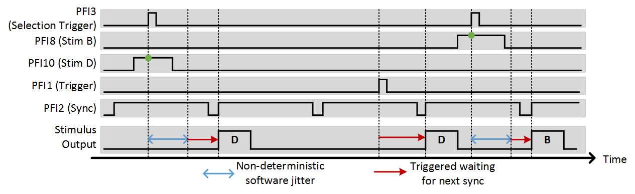
The external stimulus selection capability allows complete control of the photostim module using external digital signals. This is ideal if a separate system is controlling the experiment and needs to be able to command certain stimuli with digital triggers. To utilize this feature, PFI terminals are assigned to stimuli using the “Terms” and “Stimuli” settings. For example, if “Terms” is set to “7 8 9 10” and stimuli is set to “1 2 3 4”, PFI terminal 7 indicates that stimulus 1 should be output, ect. The last option that needs to be set is the trig term. This is the terminal that triggers the selection operation. The following example shows the experimental setup and the behavior that results.
Photostim Motion Correction
In a dual scan path configuration for simultaneous imaging (resonant-galvo) and photostimulation (galvo-galvo), sample motion can result in off-target stimulation. To compensate for this effect, ScanImage® can detect sample motion and re-target the stimulation laser to track the sample.
For vDAQ based systems since ScanImage 2023.1.0, motion correction is performed by updating the offset on the analog output controlling the galvo scanners, so no additional hardware configuration is required!
For National Instruments based microscopes, an optional microscope configuration can be applied for Motion Correction during Photostimulation.
Galvo Controller Board Configuration
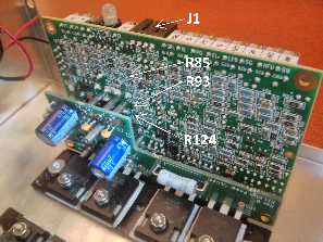
Locations of the resistors R85, R93 and R124 on a Cambridge Technologies 671 series galvo controller.
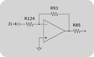
Offset input circuit of a Cambridge Technologies 671 series galvo controller. R85, R93 and R124 might be unpopulated or zero-ohm resistors. To enable the controller board’s offset input, these resistors need to be added / replaced.
Standard Cambridge Technologies 671 series galvo controller accept two input signals:
Galvo Position
Galvo Position Offset
ScanImage® controls the stimulation pattern using the Galvo Position signal. To correct for sample motion, ScanImage® uses the Galvo Position Offset Signal, which is updated independently of the Galvo Position signal.
Note
While standard Cambridge Technologies 671 series galvo controllers support position offset inputs, this functionality is disabled by default. Check if resistors R85, R93 and R124 are installed on the galvo controller board. If the resistors are unpopulated and/or zero-ohm resistors (label 000 or 0000) are installed, the controller board ignores signals provided to the offset input (pin J1.4).
In this case, follow the instructions in this section to reconfigure your galvo controller board.
Warning
Modifying the galvo controller board might void the warranty and might damage your board. The information on this page is provided to our best knowledge. However, we do not assume any responsibility in case the suggested modifications result in any hardware damage.
R124 and R93 determine the gain of the inverting amplifier shown in the figure on the right. Since NI DAQ boards can drive analog outputs +-10V, no additional amplification is required. Using the formula Vout = -Vin * R93/R124 it can be seen, that R93 and R124 should be selected to have the same value (20kOhm should be sufficient for most applications).
To determine R85, review page 13 of the Series 671 instruction manual:
R85 = ((+Offset In - -Offset In) x R54 x (R29/(R30+R119)))/(Position Output Scale Factor x Position Offset Range)

Standard values are

Offset In = 10V
R54 = 10kOhm
R29 = 10kOhm
R30 = 19kOhm
R119 = 1kOhm
Position Output Scale Factor = 0.5V /° mechanical

Choose the position Offset Range in °mechanical to select the offset range.
Wiring
To use motion correction the following signals need to be connected:
XY Galvo Position (see Configuring LinScan)
XY Galvo Position Offset
XY Galvo Position Feedback
The XY Galvo Position Feedback is used to calibrate the position offset signal relative to the galvo position signal.
The galvo position and offset inputs are located on connector J1 of the Cambridge Technologies galvo controller board. Assuming these inputs are configured to be non-inverting single ended (W4 1-3 and 4-6 jumpered), the following wiring scheme can be used:
Pin |
Signal |
MDF Section |
MDF Variable |
Recommended MDF Value |
J1.2 |
(X,Y) |
Signal GND |
||
J1.3 (X) |
X Galvo position |
LinScan |
XMirrorChannelID |
0 |
J1.3 (Y) |
Y Galvo position |
LinScan |
YMirrorChannelID |
1 |
J1.4 (X) |
X Galvo position offset |
LinScan |
XMirrorOffsetChannelID |
0 |
J1.4 (Y) |
Y Galvo position offset |
LinScan |
YMirrorOffsetChannelID |
1 |
J4.2 (X) |
X Galvo position feedback |
LinScan |
XMirrorPosChannelID |
5 |
J4.2 (Y) |
Y Galvo position feedback LinScan YMirrorPosChannelID 6 |
Photodiode feedback / Photostim |
BeamAiId |
7 |
J4.3 (X,Y) |
Signal GND |
Note
The DAQ device that drives the X and Y galvo position offset signals is configured in the LinScan MDF variable ‘deviceNameOffset’. Any NI DAQ board with two analog outputs can be used (E,S,M,X series).
While USB-DAQ boards are supported, PCI/PXI based boards are recommended. Updating the offsets using an USB-DAQ device introduces additional latency into the offset correction (~15ms), whereas the latency using PCI/PXI based devices is negligible (~2us).
MDF Configuration
%% LinScan
deviceNameAcq   = 'PXI1Slot3';      % string identifying NI DAQ board for PMT channels input
deviceNameGalvo = 'PXI1Slot3';      % string identifying NI DAQ board for controlling X/Y galvo. leave empty if same as deviceNameAcq
deviceNameAux   = 'PXI1Slot3';      % string identifying NI DAQ board for outputting clocks. leave empty if unused. Must be a X-series board

%Scanner position feedback
XMirrorPosChannelID = 5;            % The numeric ID of the Analog Input channel to be used to read the X Galvo position (optional).
YMirrorPosChannelID = 6;            % The numeric ID of the Analog Input channel to be used to read the y Galvo position (optional).

%Scanner control
XMirrorChannelID = 0;               % The numeric ID of the Analog Output channel to be used to control the X Galvo.
YMirrorChannelID = 1;               % The numeric ID of the Analog Output channel to be used to control the y Galvo.

% (optional) Mirror position offset outputs for motion correction
deviceNameOffset = 'Dev1';          % string identifying NI DAQ board that hosts the offset analog outputs
XMirrorOffsetChannelID = 0;         % numeric ID of the Analog Output channel to be used to control the X Galvo offset.
YMirrorOffsetChannelID = 1;         % numeric ID of the Analog Output channel to be used to control the y Galvo offset.
XMirrorOffsetMaxVoltage = 1;        % maximum allowed voltage output for the channel specified in XMirrorOffsetChannelID
YMirrorOffsetMaxVoltage = 1;        % maximum allowed voltage output for the channel specified in YMirrorOffsetChannelID

%% Photostim
photostimScannerName = 'LinScan';   % Name of scanner (from first MDF section) to use for photostimulation. Must be a linear scanner
%Monitoring DAQ AI channels
BeamAiId      = 7;                  % AI channel to be used for monitoring the Pockels cell output
Operation
Tip
After configuring the system, it is essential to calibrate the Photostim Position Signal, Position Offset Signal and Feedback Signal. Since the calibration settings persist between ScanImage® sessions, this step needs to be done only once,
To enable sample tracking, perform the following steps:
Start the Photostimulation module by selecting ‘Start’ in the Photostimulation Controls window
Start a Focus/Grab/Loop
Right click the live image in one of the channel display windows and select ‘Set motion correction reference’
Right click the live image in one of the channel display windows and select ‘Enable motion correction’
(Optional) Right click the live image in one of the channel display windows and select ‘Show motion’
(Optional) Enable the ‘Monitor Show’ option in the Photostimulation Controls window
The Photostimulation module is now tracking the sample by updating the offset signal whenever motion is detected.
SLM Photostimulation
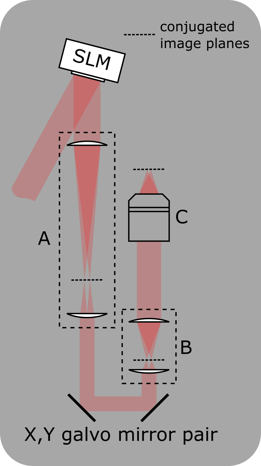
Setup for integrating an SLM into the photostimulation path
A: Telescope to demagnify the beam onto the X,Y-galvo mirrors
B: Scan lens and tube lens
C: Objective
A zero-order beam block can be added at the conjugated image plane in telescope A
For a more detailed schematic see
Nikolenko, V. et al. SLM Microscopy: Scanless two-photon imaging and photostimulation with spatial light modulators. Front. Neural Circuits 2, 5 (2008).
ScanImage’s photostimulation module supports simultaneous multi-site stimulation by utilizing a phase-only SLM for wavefront shaping. Since the SLM update rate and the achievable scan angle of the SLM are limited, the SLM can be used in series with two galvanometer mirrors, which allow to scan the projected dots over the sample.
Setup
A detailed description of adding an SLM to the photostimulation path can be found in the following publication:
Nikolenko, V. et al. SLM Microscopy: Scanless two-photon imaging and photostimulation with spatial light modulators. Front. Neural Circuits 2, 5 (2008).
Registration
To ensure accurate targeting, the Galvo/Galvo path, the SLM path and additional imaging paths need to be aligned to each other. ScanImage® includes an Alignment Tool for this purpose. After configuration, the SLM path will show up as a scanner for imaging in the configuration window.
Zero order diffraction
The diffraction efficiency of any SLM is typically below 100%. This means that a portion of the incident light remains undiffracted and contributes to the zero order diffraction spot in the image plane. Typically, this zero order diffraction spot is undesired. The most common techniques to mitigate this effect are
Block the zero order spot in a conjugated image plane using a reflective dot on a window.
Defocus the zero order spot to shift the energy outside the sample or at least outside the region of interest. The SLM can be used to compensate for the defocus during a photostimulation.
For the second solution, ScanImage® allows to define a static offset in the GUI, which can be used to compensate for the defocus.
Output Files
If the option is enabled to log information in the photostimulation controls window, a .stim file will be created. The photostimulation log file (.stim) contains a sequence of numbers that is parsed into Nx3 array with three variables, the X coordinate, the Y coordinate, and the beam power. The file can be read using the function scanimage.util.readPhotostimMonitorFile(filename).
1out = scanimage.util.readPhotostimMonitorFile('filename')
2
3% x,y are in reference coordinate space, beam power is in [V], native readout of photo diode
4
5out.X = phtstimdata(:,1);
6out.Y = phtstimdata(:,2);
7out.Beam = phtstimdata(:,3);