Multiple Region of Interest (MROI) Imaging
ScanImage® allows the full field of view of the microscope to be subdivided into multiple regions of interest (ROIs).
Benefits
The use of ROIs offers the following advantages:
Frame Rate Optimization
Limiting tissue exposure
Tracing features through a volume
Frame Rate Optimization
In a laser scanning microscope scanning a single large range within the field of view, the frame rate is calculated as follows:

To increase the frame rate, the
line rate can be increased
Resonant Scanning: faster resonant scanner
Linear Scanning:
decrease pixels per line
decrease pixel bin factor
increase sample rate
the number of lines per frame can be decreased
the duration alotted for frame flyback time can be decreased
Increasing the frame rate while scanning a single large region can lead to lower image resolution in a field of view which may only have a few, smaller regions of interest. Multiple ROI scanning can maximize the frame rate by skipping image regions of low interest while preserving good image resolution individual ROIs.
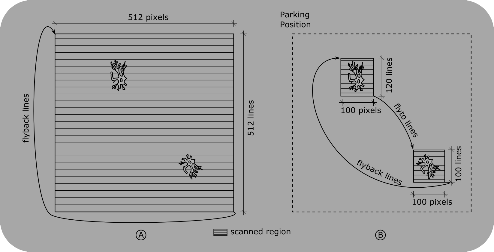
Full Field of View vs. ROIs
A: When scanning the full field of view, regions of low interest contribute to the frame period and therefore decrease the frame rate.
B: By defining regions of interests (ROIs) the number of scanned lines is reduced to maximize the frame rate while preserving the image resolution within the ROIs
Limiting Tissue Exposure
ScanImage® allows to control the laser power by using Pockels cell in the optical path. By fully attenuating the beam power while traversing between ROIs, the exposure of tissue is minimized. Additionally, ScanImage® allows beam power to be set differently for each ROI; More sensitive scanned areas can be given less power.
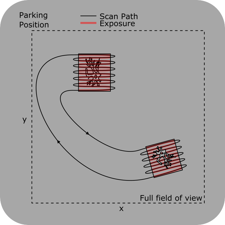
Tissue Exposure
Tissue is only exposed to the laser while image data is acquired.
The beam is attenuated in between regions of interest.
Tracing of features through a volume
An ROI in the context of ScanImage acquisition is a collection of imaging planes at different z-planes called scanfields. With ScanImage’s MROI feature, the user can define scanfields at multiple cross sections. A scanfield is defined by x,y position, x,y extent, rotation and resolution. It is sufficient to define scanfields at an ROI’s top and bottom cross sections since ScanImage® interpolates scanfields within the volume as needed.
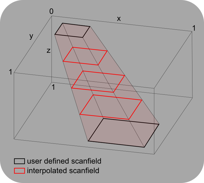
Tracing Stack
By defining multiple scanfields at different z-planes of a ROI, features can be traced through a volume.
Using MROI
ScanImage determines scan paths and timing from ROI data.
Each ROI is a collection of scanfields. The number and definition of the scanfields is the bulk of what shapes an ROI. Scanfields used for scanning are rectangles representing the bounding box for the scan at a particular depth. An ROI with a single scanfield has infinite depth upwards and downwards, so all depths will scan within that scanfield. An ROI with 2 or more scanfields has finite depth set by the depths of the top and bottom scanfield.
If it is desired to only image at the depths of the defined scanfields, then the ROI property discrete mode can be enabled. Otherwise, slices taken between defined scanfields will produce images at bounds that are linearly interpolated between the nearest scanfields.
Below is a tutorial to go over the workflow involved in MROI scanning.
Acquire reference images
To configure MROI for a given sample, first start with a Focus acquisition without
MROI enabled to find the sample, set beam power, and adjust image quality.
Alternatively, a stack can be grabbed and then used to draw ROIs relative
to a context volume.
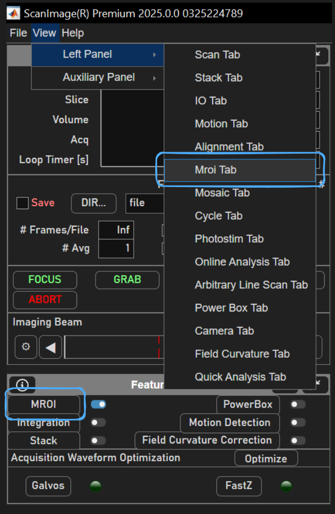
Next, Bring up the MROI tab either via the View menu or the button in the Features GUI.
Tip
Imaging can be done at 1x zoom, 0.9 spatial fill fraction, high pixel resolution, and display frame averaging for a quality reference image making use of most of the scanners’ available range.
Focus will display image data in the viewport. Image data can be pinned to background of the viewport by right clicking and navigating to
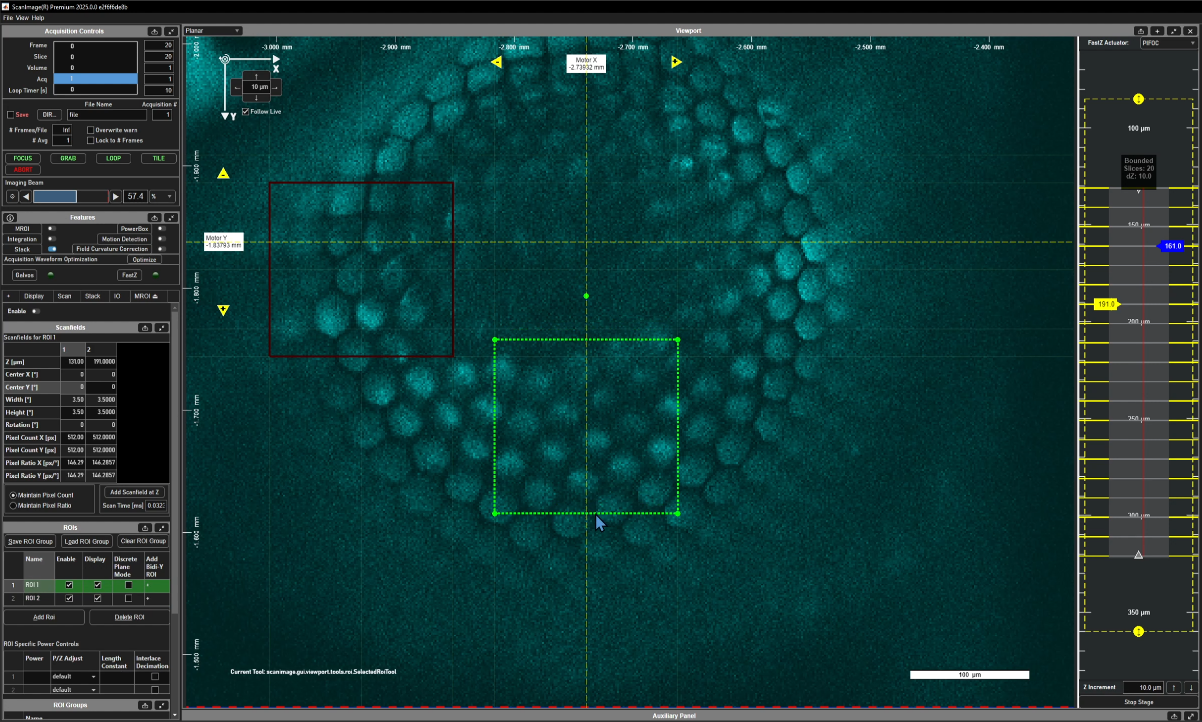
Add ROIs and scanfields
clicking the Add ROI
button in the ROI panel allows the user to draw a Rotated Rectangle ROI
over the range of interest in the pinned image by clicking and dragging over the display.
Shown below are two scanfields at the same depth, each belonging to separate ROIs.
Note
The location, width, height, and rotation of drawn ROIs are limited by the selected imaging system’s scanner configuration. See the Scanner Configurations page for more details.
This tutorial is done with an RGG scanhead configuration, which yields the highest frame rates and leverages the X galvo to offset the X location of the center of scanfields.
Newly created ROIs by default will cover an infinite Z range such that stacks with any slices above and below the defined scanfield will be imaged. To refine an ROI to a smaller range of Zs, the yellow display slider can be used to change the currently viewed depth of the Viewport, then click and drag the the previously defined scanfield denoted with the dashed outline to add a scanfield at the new depth. One could also select the ROI to bound from the ROI Gui before clicking ‘Add Scanfield at Current Z’ from the Scanfields GUI to achieve the same thing.
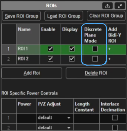
If it is desired to image only at the depths where scanfields are defined, Discrete Plane Mode can be enabled. To do so, one can place a check in the Discrete Plane Mode column for the row of the ROI of interest.
For more than 2 depths for an ROI, each additional depth outside of the current top and bottom scanfields requires the user to click the Add ScanField at Current Z button.

Configure ROIs Acquisition parameters
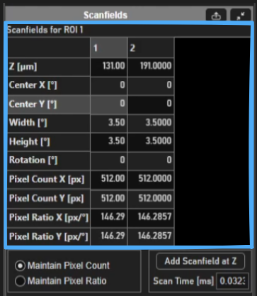
To precisely specify scanfield properties such as width, height, center position, rotation, and pixel resolution in X and Y, edit the rows of the table in the Scanfields GUI after selecting an ROI from the table in the ROIs GUI.
ROIs can also be configured to use ROI specific powers apart from what was defined from the beams slider in the acquisition controls gui via editing the ROI specific powers table in the ROI GUI after selecting the ROI from the table.
ROI Specific Power Controls |
These parameters allow specifically controlling the power of an ROI. If any of the values are unset, the parameters from the beams sliders in the acquisiton controls GUI and the power vs depth settings from the Power Vs Depth GUI are used. |
Powers |
Laser power. If there are multiple pockels cells, a value for each should be entered separated by commas |
P/z Adjust |
Dropdown of four power vs. depth adjustment types:
|
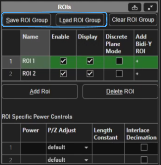
Once the ROIs have been completely defined, the user can save the ROI Group
for later acquisitions. To do so, click the Save ROI Group button and follow the saving wizard.
Later, the ROI Group can be reloaded using Load ROI Group.
Note
it is possible for ROIs to intersect.
Acquiring
To acquire the multiple regions of interest,
place a check in the Enable MROI checkbox located
at the top of the MROI tab or in the Features GUI.
If a 2D acquisition of a single depth is desired, then
ensure that the current sample position as indicated in the ZView of the Viewport
intersects with at least one of the defined 3D ROIs
or exactly matches a scanfield of a discrete mode enabled ROI.
Then, select one of the Focus, Grab, or Loop acquisition buttons
from the Acquisition Controls GUI window.
Acquisition can fail at this point for few reasons:
1. If executing a planar acquisition without stack enabled and the current sample position does not interesect a 3D ROI or coincide with one of the scanfields of a discrete ROI, 2. If executing a slowZ stack and one or more slices do not intersect a 3D ROI or coincide with a discrete ROI’s scanfields 3. if executing a fastZ stack and none of the slices interesect the 3D ROI or coincide with a discrete ROI’s scanfields
Tip
If there is a wide gap between ROI’s Zs, it may improve volume scan rate to use the step waveform rather than the sawtooth waveform.
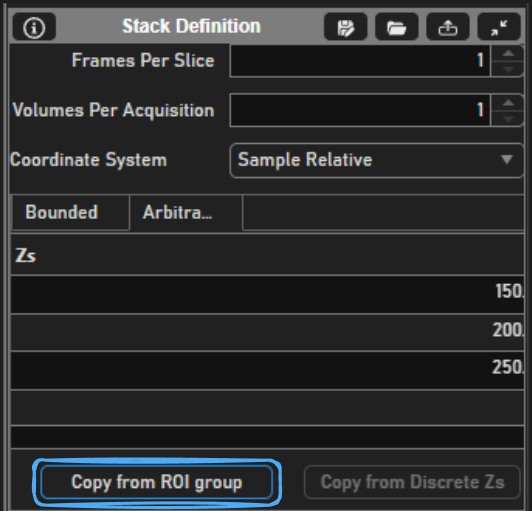
If discrete mode is enabled, users can make use of the button Copy from ROI group under the Arbitrary stack definition tab.
Just also note that fastZ stacks taken in with an arbitrary stack definition must be taken using a step fastZ waveform rather than the sawtooth fastZ waveform.
Output File
The output of an MROI acquisition is a TIFF with metadata concerning each of the ROIs contained. Each ROI’s image for a given plane will be stacked one on top of the other seamlessly in the image.
See the ScanImage® BigTiff Specification page for the big Tiff specification.