SLM Diffraction Efficiency Calibration
Substage Camera Setup
ScanImage:
As a diffraction-limited point projected by an SLM is steered farther away from the SLM’s zero order spot, the brightness of the point falls off. The exact profile of the fall off depends on multiple factors such as the accuracy of the SLM LUT and the alignment of the microscope. For optogenetic experiments, the varying intensity poses a challenge, as the cells should be illuminated with a known intensity. To overcome this challenge, ScanImage® includes a tool to map the diffraction efficiency of the SLM over a 3D field of view.
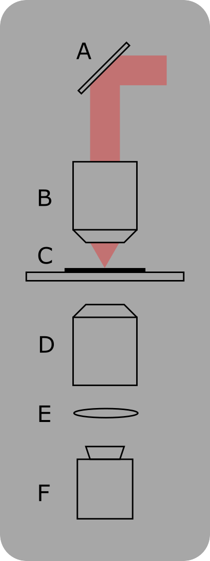
A homogeneous, thin-film fluorescent sample is positioned under the microscope. The SLM illuminates the sample at a given X/Y position sweeps the Z focus through the sample, while the camera records an image for each Z position to form a point spread function. The sample is then moved to a different Z position by a stage, and the process is repeated until a sufficient number of points in the 3D field of view are surveyed. A polynomial function is then fit to the XYZ-intensity values. During a photostimulation experiment, the calibration is used to adjust the global laser power and the intensity weights of the holographic points for an even illumination.
Note
See the Cameras documentation page to get a list of supported cameras in ScanImage.
In the SLM controls, select ‘Align’, then ‘Diffraction Efficiency - Show Calibration Utility’.
Calibration Steps
Calibrate Camera
The camera is used for intensity calibration. Dark current, static pixel offsets and dead pixels need to be calibrated before the intensity measurement. Ensure no light reaches the camera sensor and select ‘Camera - Calibrate’.
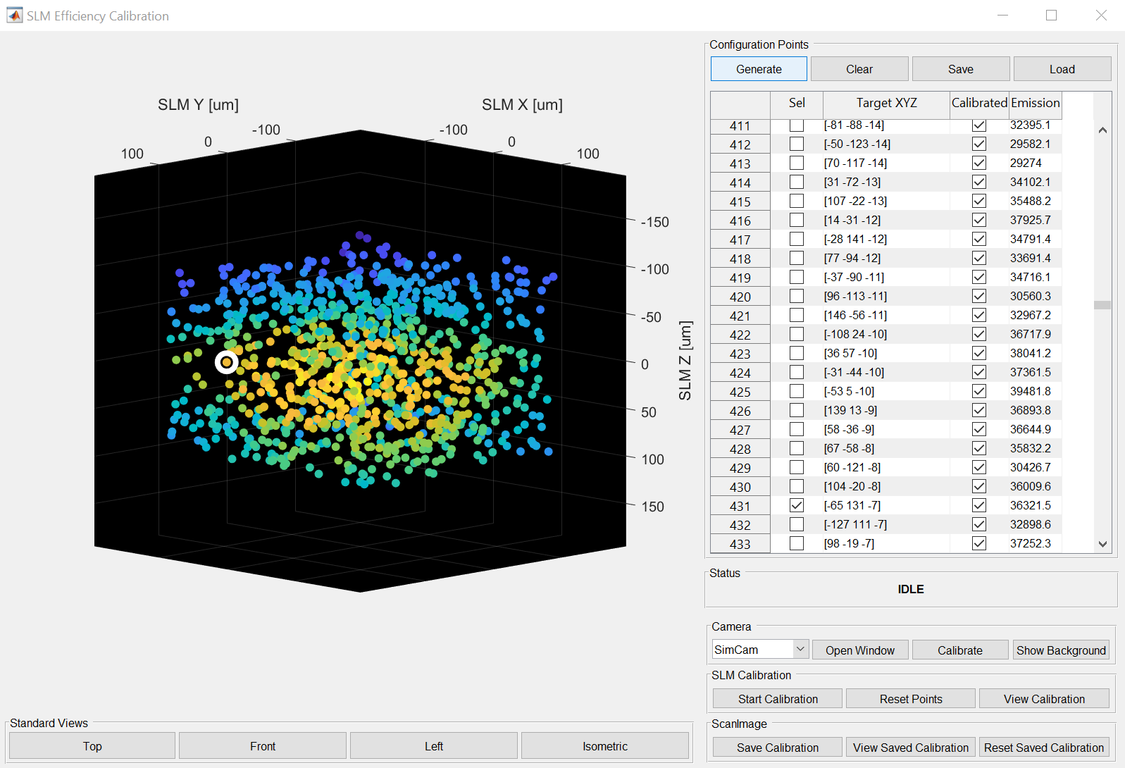
Generate Point Cloud
Select ‘Configuration Points - Generate’. The following dialogs allow to configure and generate a cloud of calibration points within the 3D volume. The parameters allow to configure the number of points and the extent of the points in XYZ. If a zero order beam block is present in the system, it can be excluded from the measurement.
Calibration
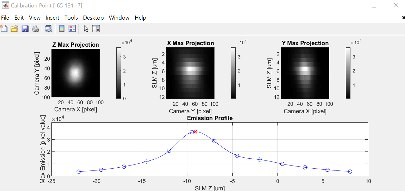
Select ‘SLM Calibration - Start Calibration’. The calibration can use a motorized stage or a FastZ actuator for the calibration. The first two points in the cloud need to be found manually by moving the FastZ / Stage. The remaining points are calibrated automatically. The PSF of calibrated points can be explored by double clicking on the point.
Inspection and Saving.
Select ‘SLM Calibration - View Calibration’. The fitted polynomial can be explored by dragging the red cursor lines. If the calibration is satisfactory, select ‘ScanImage® - Save Calibration’.